budzique
Member
- Joined
- Jun 28, 2020
- Messages
- 75
- Reaction score
- 69
- Points
- 18
Very nice! What software are you using for schematic capture and board layout?
George
Correct, this is easyedaGuessing EasyEDA, based on the screenshots
The car lovers social network
Automotive components
Create videos that captivate
Automotive Hot or Not
Vehicle hacker protection
By enthusiasts, for enthusiasts
Advertise with us!
Timing is everything
Get the best deals on wheels!
Vehicle Specific Solutions
Brands you can trust
Promo code: REDLINE
Kia Hyundai Auto Racing
Authentic Tuning

Very nice! What software are you using for schematic capture and board layout?
George
Correct, this is easyedaGuessing EasyEDA, based on the screenshots

memFuture2Addr is the variable for the address in eeprom to be accessed. the error is "isg" on that line. it's supposed to be the variable "ahold"You’re writing the future state of auto hold over the eeprom value of the state for ISG (Idle Stop and Go)?


I’ve got the fabrication down. I considered wireless communication however it would increase production cost as well as R&D. I’m trying to keep this competitively priced.Do you need a hand with this? I've done a lot of Arduino work, and my own PCB design, including full fabrication.
I've also done Bluetooth Low Energy and WiFi, so that could tie into a phone app for settings.
This is true, I’m going to offer pre-programming service as-well, I have a website all setup for sale of these since multiple Facebook groups and forum members have shown interest, just waiting on approval to get vendor statusAlso, if you use a 32u micro you don't need the USB bridge.
It is planned for a future version, however I need to hook up my scope because it's not a "normally high switch" like the other buttons interfaced. I've been working with a friend on a pro version of the ksdm with a ton of other features, but likely we won't have it ready until close to end of year.Now that I think about this, I have a GTS and drive around in Sport+ mode during good weather. It is enabled by holding down the traction control button for roughly 5 seconds. Any possibility that this can be added? I'd even go for using the output for Autohold to be used for the traction control button.
Thanks,
George
So I got pretty deep into AVR programming and I like your thoughts on interrupts vs polling. I wrote some code for an extremely low power module (note: this code includes all my latest hardware updates including optocouplers and FRAM so it may seem different)Thanks a bunch for doing the design work on this, I'm excited to try making my own.
I spent a little time this morning re-writing the software to be able to use interrupts or polling, but I haven't tested it on my car yet, so typos are likely.
A nano only has 2 interrupt capable pins, so polling would be eventually required for ISG (Idle Stop and Go) operation. Other chips like a teensy could use interrupts, but in a case like this, I think a tight polling loop is fine.
C:#include <Arduino.h> #include <EEPROM.h> // how long we need to wait between changing modes automatically (in milliseconds) #define OUTPUT_WAIT_TIME_MS 1000 // how long we need to hold the button down when changing modes automatically (in milliseconds) #define OUTPUT_PULSE_TIME_MS 250 // how long it takes the car to start up (in milliseconds) #define STARTUP_WAIT_TIME_MS 5000 // intput pins #define CW_INPUT_PIN 2 #define CCW_INPUT_PIN 3 // output pins #define CW_OUTPUT_PIN 5 #define CCW_OUTPUT_PIN 6 // enable debug messages #define DEBUG // debug print wrapper #ifdef DEBUG #define DEBUG_PRINT(x) Serial.println(x) #else #define DEBUG_PRINT(x) #endif #define INTERRUPTS //#define POLLING // memory address we store the mode in (not currently wear leveled, will handle ~100,000 mode changes) int EEPROM_ADDRESS_MODE = 0; // memory address we mark to signify first startup int EEPROM_ADDRESS_INITIAL_SETUP = 1; const byte MODE_FIRST = 0; const byte MODE_SMART = 0; const byte MODE_ECO = 1; const byte MODE_COMFORT = 2; const byte MODE_SPORT = 3; const byte MODE_CUSTOM = 4; const byte MODE_LAST = 4; const byte MODE_IMPOSSIBLE = 255; // global that stores current car mode byte currentMode = MODE_IMPOSSIBLE; // global that stores current target mode byte targetMode = MODE_IMPOSSIBLE; void update_eeprom(void) { // only update eeprom if data is different (prevent eeprom wear) if (EEPROM.read(EEPROM_ADDRESS_MODE) != currentMode) { EEPROM.write(EEPROM_ADDRESS_MODE, currentMode); DEBUG_PRINT("EEPROM Update"); DEBUG_PRINT(currentMode); } } // capture a cw physical knob turn void knob_cw(void) { currentMode -= 1; if (currentMode < MODE_FIRST) currentMode = MODE_FIRST; } // capture a ccw physical knob turn void knob_ccw(void) { currentMode += 1; if (currentMode > MODE_LAST) currentMode = MODE_LAST; } // simulate a clockwise turn of drive mode num times void clockWise(int num) { for (int i = 0; i < num; i++) { digitalWrite(CW_OUTPUT_PIN, HIGH); delay(OUTPUT_PULSE_TIME_MS); digitalWrite(CW_OUTPUT_PIN, LOW); delay(OUTPUT_PULSE_TIME_MS); DEBUG_PRINT("Automated CW"); } } // simulate a counterclockwise turn of drive mode num times void counterClockWise(int num) { for (int i = 0; i < num; i++) { digitalWrite(CCW_OUTPUT_PIN, HIGH); delay(OUTPUT_PULSE_TIME_MS); digitalWrite(CCW_OUTPUT_PIN, LOW); delay(OUTPUT_PULSE_TIME_MS); DEBUG_PRINT("Automated CCW"); } } void setup() { // must use pins 2 and 3 for interrupts on an nano pinMode(CW_INPUT_PIN, INPUT_PULLUP); // clockwise input pinMode(CCW_INPUT_PIN, INPUT_PULLUP); // counterclockwise input pinMode(CW_OUTPUT_PIN, OUTPUT); // clockwise output pinMode(CCW_OUTPUT_PIN, OUTPUT); // counterclockwise output // if this is the first use set the default drive mode, car is expected to be in comfort mode if (EEPROM.read(EEPROM_ADDRESS_INITIAL_SETUP) != 1) { DEBUG_PRINT("First Boot"); EEPROM.write(EEPROM_ADDRESS_MODE, MODE_COMFORT); EEPROM.write(EEPROM_ADDRESS_INITIAL_SETUP, 1); // mark initial setup as done targetMode = MODE_COMFORT; } else { DEBUG_PRINT("EEPROM Loaded"); targetMode = EEPROM.read(EEPROM_ADDRESS_MODE); DEBUG_PRINT(targetMode); // car remembers eco and comfort settings if (targetMode == MODE_ECO || targetMode == MODE_COMFORT) currentMode = targetMode; else currentMode = MODE_COMFORT; } #ifdef DEBUG Serial.begin(115200); #endif // wait for car to start up delay(STARTUP_WAIT_TIME_MS); // change the car mode if needed if (targetMode < currentMode) counterClockWise(currentMode - targetMode); if (targetMode > currentMode) clockWise(targetMode - currentMode); currentMode = targetMode; #ifdef INTERRUPTS // watch for the mode to change attachInterrupt(digitalPinToInterrupt(CW_INPUT_PIN), knob_cw, FALLING); attachInterrupt(digitalPinToInterrupt(CCW_INPUT_PIN), knob_ccw, FALLING); #endif } void loop() { #ifdef POLLING // poll cw static bool previous_cw = true; bool cw = digitalRead(CW_INPUT_PIN); if (cw == false && cw != previous_cw) knob_cw(); previous_cw = cw; // poll ccw static bool previous_ccw = true; bool ccw = digitalRead(CCW_INPUT_PIN); if (ccw == false && ccw != previous_ccw) knob_cw(); previous_ccw = ccw; #endif update_eeprom(); }
#include <avr/sleep.h>
#include <EEPROM.h>
// Nominal input Values
#define NOM_PIN3 1
#define NOM_PIN4 1
#define NOM_PIN7 1
#define NOM_PIN9 0
// some arduinos have issues with pulling ground to some pins upon startup.
#define ERROR_OFFSET 1
// Set time to wait before outputing memory to vehicle in ms (recommended
// 2000-5000)
#define STARTUP_WAIT_TIME 4000
int memAddress = 0;
int memSetupAddr = 1;
int memgsiAddr = 2;
int memFuture2Addr = 3;
const byte SMARTMODE = 0;
const byte ECOMODE = 1;
const byte COMFORTMODE = 2;
const byte SPORTMODE = 3;
const byte CUSTOMMODE = 4;
byte currentMode;

bool ahold = false;
bool gsi = true;
byte memRead(int addr) {
  byte r;
#ifdef USE_FRAM
  nvRAM.readByte(addr, &r);
#else
  r = EEPROM.read(addr);
#endif
  return r;
}
void memSave(int addr, byte value) {
#ifdef USE_FRAM
  nvRAM.writeByte(addr, value);
#else
  EEPROM.write(addr, value);
#endif
}
// simulate a clockwise turn of drive mode num times
void clockWise(int num) {
  for (int i = 0; i < num; i++) {
    digitalWrite(5, HIGH);
    delay(250);
    digitalWrite(5, LOW);
    delay(250);
  }
}
// simulate a counterclockwise turn of drive mode num times
void counterClockWise(int num) {
  for (int i = 0; i < num; i++) {
    digitalWrite(6, HIGH);
    delay(250);
    digitalWrite(6, LOW);
    delay(250);
  }
}
ISR(PCINT2_vect){
  if (digitalRead(3) != NOM_PIN3){
    if (currentMode <= SMARTMODE) {
      currentMode = SMARTMODE;
    } else {
      currentMode--;
    }
    memSave(memAddress, currentMode);
  }
  if (digitalRead(4) != NOM_PIN4){
    if (currentMode >= CUSTOMMODE) {
      currentMode = CUSTOMMODE;
    } else {
      currentMode++;
    }
    memSave(memAddress, currentMode);
  }
  if (digitalRead(7) != NOM_PIN7){
    gsi = !gsi; // reverse the value from current.
    memSave(memgsiAddr, gsi);
  }
}
ISR (PCINT0_vect)
 {
  if (digitalRead(9) != NOM_PIN9){
    ahold = !ahold; // reverse the value from current.
    memSave(memFuture2Addr, ahold);
  }
 }
//############### Start point ############## //
void setup() {
  pinMode(3, INPUT_PULLUP); // clockwise input
  pinMode(4, INPUT_PULLUP); // counterclockwise input
  pinMode(5, OUTPUT);
  pinMode(6, OUTPUT);
  pinMode(7, INPUT_PULLUP); // gsi (Auto Start Stop) input
  pinMode(8, OUTPUT);
  pinMode(9, INPUT_PULLUP); // Auto Hold input
  pinMode(10, OUTPUT);
  if (memRead(memFuture2Addr)) {
    ahold = true; // enable Autohold
  }
  if (!memRead(memgsiAddr)) {
    gsi = false; // disable gsi
  }
  // If initial setup hasn't completed, set the default drive mode
  if (memRead(memSetupAddr) != 1) {
    // Write the default to permanent memory
    memSave(memAddress, COMFORTMODE);
    memSave(memSetupAddr, 1);
    currentMode = COMFORTMODE;
  } else {
    // Setup has completed read the current mode from permanent memory
    currentMode = memRead(memAddress);
  }
  delay(STARTUP_WAIT_TIME);
  switch (currentMode) {
  case SPORTMODE:
    clockWise(1 - ERROR_OFFSET);
    break;
  case CUSTOMMODE:
    clockWise(2 - ERROR_OFFSET);
    break;
  case SMARTMODE:
    counterClockWise(2 + ERROR_OFFSET);
    break;
  case COMFORTMODE:
    counterClockWise(ERROR_OFFSET);
    break;
  case ECOMODE:
    counterClockWise(ERROR_OFFSET);
    break;
  default:
    break;
  }
  if (ahold) {
    digitalWrite(10, HIGH);
    delay(250);
    digitalWrite(10, LOW);
  }
  // if gsi is disabled in memory, send a signal. gsi is on by default.
  if (!gsi) {
    digitalWrite(8, HIGH);
    delay(250);
    digitalWrite(8, LOW);
  }

  PCMSK2 |= bit (PCINT19);  // Attach pin 3
  PCMSK2 |= bit (PCINT20);  // Attach pin 4
  PCMSK2 |= bit (PCINT23);  // Attach pin 7
  PCMSK0 |= bit (PCINT1);   // Attach pin 9
  PCIFR  |= bit (PCIF0);    // Disable prior interrupts on PCINT0_vect
  PCICR  |= bit (PCIE0);    // Enable new interrupts on PCINT0_vect
  PCIFR |= bit (PCIF2);     // Disable prior interrupts on PCINT0_vect
  PCICR |= bit (PCIE2);     // Enable new interrupts on PCINT0_vect
}
void loop() {
  set_sleep_mode (SLEEP_MODE_PWR_DOWN);  // Put the CPU into low power sleep mode
  sleep_mode ();
}

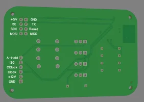
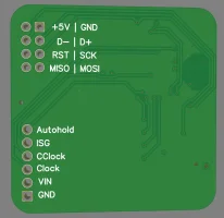
I'm developing a KSDMPRO module that will do a ton of stuff from auto-setting the parking brake (if you have electronic parking brake) to optionally disabling traction and stability when you enter custom mode (IE Track Mode), to "hacking" the ambient lighting to change color based on drive mode, and expanded capabilities such as seat memory. There's a ton of development, it uses the massive ATMEGA2560 microcontroller as the ATMEGA328 I used in the KSDM3 is unable to handle that many input/outputs. as far as timing goes, I don't have a prototype yet, I plan on ordering some engineering samples and testing them before the end of the year. There's a ton more math, and I still need to translate the CANBUS commands so the ambient lighting doesn't revert back moments after the command is sent. here's a bit of a teaser of what the final product will look like:Great work. Being in Michigan, I am really looking for heated seats and steering wheel (to turn on with OEM remote start). I saw you said that may be planned for the future. If it is able to be done, any idea on timing? I wouldn't want to get one module and have to replace it in only a few months. Thanks a lot.

Damn really good stuff. Can’t wait for the ksdmproI'm developing a KSDMPRO module that will do a ton of stuff from auto-setting the parking brake (if you have electronic parking brake) to optionally disabling traction and stability when you enter custom mode (IE Track Mode), to "hacking" the ambient lighting to change color based on drive mode, and expanded capabilities such as seat memory. There's a ton of development, it uses the massive ATMEGA2560 microcontroller as the ATMEGA328 I used in the KSDM3 is unable to handle that many input/outputs. as far as timing goes, I don't have a prototype yet, I plan on ordering some engineering samples and testing them before the end of the year. There's a ton more math, and I still need to translate the CANBUS commands so the ambient lighting doesn't revert back moments after the command is sent. here's a bit of a teaser of what the final product will look like:
View attachment 51271
(50mm x 50mm)
9 channels of input/output memory or triggers (marked with ->)
- Drive Mode L
- Drive Mode R
- ISG (Idle Stop and Go)
- Autohold
- Park Signal -> EPB (Electronic Parking Brake)
- Heated Driver Seat
- Cooled Driver Seat (or Heated Passenger Seat)
- Heated Steering Wheel
- (Drive Mode==CUSTOM) -> Traction Control
This thing is an absolute unit, and I want to pack it with as many features as possible, so we are looking at months. but the KSDM3 will be ready in the next week on my website
What's your website address?I'm developing a KSDMPRO module that will do a ton of stuff from auto-setting the parking brake (if you have electronic parking brake) to optionally disabling traction and stability when you enter custom mode (IE Track Mode), to "hacking" the ambient lighting to change color based on drive mode, and expanded capabilities such as seat memory. There's a ton of development, it uses the massive ATMEGA2560 microcontroller as the ATMEGA328 I used in the KSDM3 is unable to handle that many input/outputs. as far as timing goes, I don't have a prototype yet, I plan on ordering some engineering samples and testing them before the end of the year. There's a ton more math, and I still need to translate the CANBUS commands so the ambient lighting doesn't revert back moments after the command is sent. here's a bit of a teaser of what the final product will look like:
View attachment 51271
(50mm x 50mm)
9 channels of input/output memory or triggers (marked with ->)
- Drive Mode L
- Drive Mode R
- ISG (Idle Stop and Go)
- Autohold
- Park Signal -> EPB (Electronic Parking Brake)
- Heated Driver Seat
- Cooled Driver Seat (or Heated Passenger Seat)
- Heated Steering Wheel
- (Drive Mode==CUSTOM) -> Traction Control
This thing is an absolute unit, and I want to pack it with as many features as possible, so we are looking at months. but the KSDM3 will be ready in the next week on my website