How to Install Oil Catch Cans

When I originally saw your post

No, I have not forgotten,
went to my garage this morning, but my mechanic wanted a little more time to study up on the matter.
I respect that he is not quite comfortable with messing with a new car when he has not fully studied his manuals yet.
So I am going to give him some space and see him early next week. It's only an eight minute drive.
I'll let you know in due course. :)
 
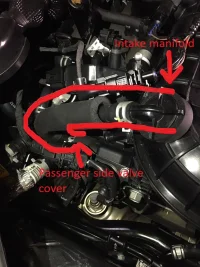
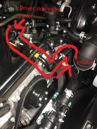
Here are images of both breather lines where the catch cans should be placed inline.
 

Attachments

  • IMG_2205.webp
    IMG_2205.webp
    233.3 KB · Views: 255
  • IMG_2206.webp
    IMG_2206.webp
    242.7 KB · Views: 239
Last edited:
I have uploaded

@GTB thank you for the pictures. I'll take them to our next meeting.
Interestingly, my KIA dealer's mechanics didn't say anything as to the cans installation, although I was told, their master mechanic had them installed on his Subaru.
So at least someone was familiar with OCCs. They had the car for 3 hours.....
I'll certainly let you know. :)
 
______________________________
@GTB Good call on the driver's side PCV!
Saw my mechanic this morning and he agrees with you on the second connection.
The passenger side connection was already identified by both of you.
The plan is to leave the cans in place and route the hoses for the driver's side near the firewall.
We'll have the installation probably finalized by next Thursday.
Again, thank you for shedding light on the puzzle.
Stay tuned! :)
 
I had only noticed one pcv hose going to intake when I took apart the pipe work to see what can be done for an intake system. Thanks GTB for sharing, I was going to order a single catch can to install but looks like 2 are needed (or single w dual inlet). It's odd that one pcv hose leads to pre-turbo tubing while the other is a post-turbo. The passenger side pcv hose doesn't look like it's as harmful as the driver side location choice, that preturbo hose would be coating the driver side turbo and the intercooler with oil.
 
From interior to exterior to high performance - everything you need for your Stinger awaits you...
@GTB Good call on the driver's side PCV!
Saw my mechanic this morning and he agrees with you on the second connection.
The passenger side connection was already identified by both of you.
The plan is to leave the cans in place and route the hoses for the driver's side near the firewall.
We'll have the installation probably finalized by next Thursday.
Again, thank you for shedding light on the puzzle.
Stay tuned! :)
No problem! :)
 
FWIW, good or bad, I know some folks install their catch cans with drains that consist basically of a hose tapped from the bottom of the catch can and extending through the engine bay as close to the pavement as possible without being visible. That way they don't have to be removed and drained periodically.

Thoughts?
 
catch cans with drains

My initial response would be, that the OCC is an integral part of the engine's vacuum system and that should be maintained. Also, the stuff that is being collected is really nasty and not really easy to wash off your hands. Why you want to drip it into the environment this day and age is beyond me. You want to handle it the same way you handle the oil out of your crankcase. There is also the matter of set & forget. This does not spell maintenance for me.
My thoughts...:)
 
The driver side is a Breather line, doesn't have a PCV. You can route both the PCV and Breather lines to the dual inlet type OCC but since the PCV is located on the opposite side of the Breather I prefer using a separate OCC for each to avoid the long hoses.
 
The driver side is a Breather line

It should be interesting to see the results of what is being collected by each can then.
It was warm enough today to clean the cans in my car, after 6,000 km.
And now I need new O-ring. The (Chinese) ones disintegrated.

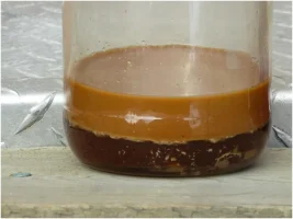
This is the result:

COMBINED FROM BOTH CANS:
I ESTIMATE THIS AMOUNT WOULD ABOUT FILL ONE CAN....

upload_2018-4-10_17-31-37.webp

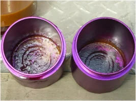
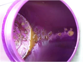
THIS IS WHAT THE BOTTOM AND SIDES OF THE CAN LOOKED LIKE:

upload_2018-4-10_17-33-14.webp
A CLOSER VIEW:

upload_2018-4-10_17-37-3.webp

I think it can't hurt to keep this crap out of your engine.....:)
 
______________________________
From interior to exterior to high performance - everything you need for your Stinger awaits you...
Twins going in tonight
 

Attachments

  • 7072A4EF-2F08-4426-942B-A0015C0169EA.webp
    7072A4EF-2F08-4426-942B-A0015C0169EA.webp
    249.7 KB · Views: 96
It should be interesting to see the results of what is being collected by each can then.
It was warm enough today to clean the cans in my car, after 6,000 km.
And now I need new O-ring. The (Chinese) ones disintegrated.

This is the result:

COMBINED FROM BOTH CANS:
I ESTIMATE THIS AMOUNT WOULD ABOUT FILL ONE CAN....

View attachment 6045

THIS IS WHAT THE BOTTOM AND SIDES OF THE CAN LOOKED LIKE:

View attachment 6046
A CLOSER VIEW:

View attachment 6047

I think it can't hurt to keep this crap out of your engine.....:)
Was the downline one less filled? As in the first one gathered more?
 
less filled

Good question!
By the looks of it, they were more or less equally filled, but the first in line seemed to have more crud in it.
My cans have a baffle in the top, separating the in & out ports. The baffles consist of two screens with holes drilled. The baffles can be unscrewed and I am planning to fill them with oil filter paper.
That might help to collect more stuff. :)
 
From interior to exterior to high performance - everything you need for your Stinger awaits you...
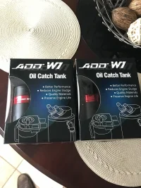
Thanks. I ponied up for the pricy ADD W1 ones that have a rather complex baffle so just curious. I got one for me and one for wife's Sorento. Both might be going into stinger to start since only 600 miles so far.

To be completely honest I was surprised to see how much crud after 3k miles only!!
 
______________________________
so just curious

Giving you something more to contemplate:
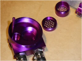
upload_2018-4-12_0-24-52.webp

INSIDE OF THE CAN’S HEAD:

TO THE LEFT THE SMALL INCOMING PORT, TO THE RIGHT THE LARGER OUTGOING PORT WITH THE DISASSEMBLED BAFFLE THAT WOULD FIT INTO THE THE LARGER HOLE.

ALL PARTS INCLUDING THE CAN ARE MACHINED FROM BILLET ALUMINUM. I CONSIDER THESE CANS WELL MADE, EXCEPT FOR THE INCLUDED HOSES WHICH COLLAPSED
AS SOON AS VACUUM WAS APPLIED
AND THE O-RING BETWEEN HEAD AND CAN, WHICH HAD TO SCRAPED OFF.
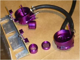
upload_2018-4-12_0-26-40.webp

THE TOPS OF THE TWO CANS WITH THE ALUMINUM BRACKET THAT THE CANS ARE MOUNTED TO – EVERYTHING UPSIDE DOWN OF COURSE.
THE STICKS STICKING UP UNSCREW FROM THE TOP AND ARE USED TO GAUGE THE CONTENT….
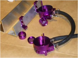
upload_2018-4-12_0-27-56.webp

THE NEW 2” x 3” ALUMINUM ANGLE FOR THE NEW BRACKET.
I LIKE TO MOUNT THE CANS A ¼” OR SO LOWER, AND I AM RUNNING OUT OF MATERIAL ON THE BOTTOM END OF THE ORIGINAL PIECE AS YOU CAN SEE.

I ALSO STARTED FILLING UP ONE OF THE BAFFLES WITH DISCS CUT FROM KITCHEN PAPER TOWEL MATERIAL.
THAT ALSO GOT ME TO THINK WHETHER THE IN & OUT PORTS SHOULD BE REVERSED.
THE FILTER MATERIAL WOULD OBSTRUCT THE INCOMING VAPORS IN THE ORIGINAL CONFIGURATION.
BY REVERSING THE PORTS, THE VAPORS WOULD HAVE AN EASY ENTRY, BUT GET FILTERED ON THEIR WAY OUT, THEREBY KEEPING THE HOSES CLEANER…:)
 
For anybody attempting to do it DIY, these are the hose sizes and correct fitting sizes you will need,
1. PCV outlet - 3/8" or -6AN <-PCV fitting
2. PCV inlet - 1/2" or -8AN <-Intake manifold
3. Breather outlet - 1/2" or -8AN <-Driver side cam cover
4. Breather inlet - 5/8" or -10AN <-Driver side intake pipe near the turbo
 
Excellent job! Thank you!
 
From interior to exterior to high performance - everything you need for your Stinger awaits you...
Back
Top