budzique
Member
- Joined
- Jun 28, 2020
- Messages
- 75
- Reaction score
- 69
- Points
- 18
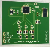
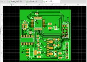
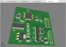
Hello, this milestone deserves a new thread, as nearly everything has changed. I'm currently working on a memory module for the drive mode selector. So far this will cost less than $50 with some assembly required.
I really want to produce a simple plug and play circuit for this, but I need testers! Please if you have the time to put this together and try it, let me know, show me your progress, show me any changes you've made
DISCLAIMER: This is very technical and requires tapping into wires, I am not responsible for anything you break by incorrectly wiring/programming this.
So here we go. as far as parts required here's the list:
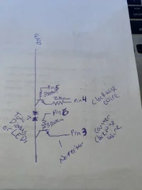
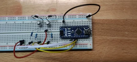
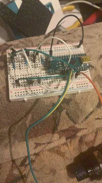
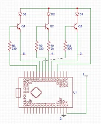
If successful your breadboard should look like a bowl of spaghetti (Note the stinger clockwise connection goes to pin 4 and counterclockwise to pin 3):
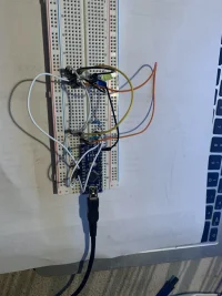
Next you'll want to load up the code:
Once programmed, make sure the car is NOT in ECO mode, and turn off the vehicle, plug the unit into a USB outlet on the car, and turn on the vehicle. If done correctly, you will see it go to sport mode, then back to comfort mode. it is now ready to record.
Troubleshooting:
I really want to produce a simple plug and play circuit for this, but I need testers! Please if you have the time to put this together and try it, let me know, show me your progress, show me any changes you've made
DISCLAIMER: This is very technical and requires tapping into wires, I am not responsible for anything you break by incorrectly wiring/programming this.
So here we go. as far as parts required here's the list:
- Arduino Nano [A000005]
- A USB for programming and later for power from the car (Later we will power it differently)
- 2x diodes, or LEDs
- 2x Positaps
- A breadboard
- A few lengths of breadboard wire.
- 2x 330ohm resistors
- 1x 2kohm resistor
- 2x 2N2222A Transistors

If successful your breadboard should look like a bowl of spaghetti (Note the stinger clockwise connection goes to pin 4 and counterclockwise to pin 3):

Next you'll want to load up the code:
C++:
#include <EEPROM.h>

// comment this out when deployed:
#define DEBUG
// some arduinos have issues with pulling ground to some pins upon startup.
#define ERROR_OFFSET 1
#define INPUT_WAIT_TIME 500
#define STARTUP_WAIT_TIME 5000

#ifdef DEBUG
#define DEBUG_PRINT(x)  Serial.println (x)
#else
#define DEBUG_PRINT(x)
#endif

int memAddress = 0;
int memSetupAddr = 1;

const byte SMARTMODE = 0;
const byte ECOMODE = 1;
const byte COMFORTMODE = 2;
const byte SPORTMODE = 3;
const byte CUSTOMMODE = 4;

byte currentMode;
unsigned long t = 0; // current time
unsigned long p = 0; // previous time


void setup() {
  pinMode(3, INPUT_PULLUP); // clockwise input
  pinMode(4, INPUT_PULLUP); // counterclockwise input
  pinMode(5, OUTPUT);
  pinMode(6, OUTPUT);
  //If initial setup hasn't completed, set the default drive mode
  if (EEPROM.read(memSetupAddr) != 1) {
    // Write the default to permanent memory
    EEPROM.write(memAddress, COMFORTMODE);
    EEPROM.write(memSetupAddr, 1);
    currentMode = COMFORTMODE;
  } else {
    // Setup has completed read the current mode from permanent memory
    currentMode = EEPROM.read(memAddress);
  }
#ifdef DEBUG
  Serial.begin(9600);
#endif

  bool modechanged = true;
  delay(STARTUP_WAIT_TIME);
  switch(currentMode){
      case SPORTMODE:
        clockWise(1-ERROR_OFFSET);
        break;
      case CUSTOMMODE:
        clockWise(2-ERROR_OFFSET);
        break;
      case SMARTMODE:
        counterClockWise(2+ERROR_OFFSET);
        break;
      case COMFORTMODE:
        counterClockWise(ERROR_OFFSET);
        break;
      case ECOMODE:
        counterClockWise(ERROR_OFFSET);
        break;
      default:
        modechanged = false;
        break;
    }
    if (modechanged){
      DEBUG_PRINT("mode has changed.");
    }


  char s[50];
  sprintf(s, "setup mode: %s", modeText(currentMode));
  DEBUG_PRINT(s);
}

void loop() {
  char c[50];
  // constantly read the input pins increment/decrement
  // the drive mode and store it in permanent memory
  if (digitalRead(4) == LOW){
    t = millis(); // get current arduino uptime.
    if (t -  INPUT_WAIT_TIME > p){ // if 1 second has bassed since last reading
      if (currentMode >= CUSTOMMODE){
        currentMode = CUSTOMMODE;
      } else {
        currentMode++;
      }
      sprintf(c, "Clock Triggered, Current Mode: %s", modeText(currentMode));
      EEPROM.write(memAddress, currentMode);
      DEBUG_PRINT(c);
      p = t; // last reading is now, set p(revious) to current time
    }
  }
  if (digitalRead(3) == LOW){
    t = millis(); // get current arduino uptime.
    if (t - INPUT_WAIT_TIME > p){ // if 1 second has bassed since last reading
      if (currentMode <= SMARTMODE){
        currentMode = SMARTMODE;
      } else {
        currentMode--;
      }
      sprintf(c, "CClock Triggered, Current Mode: %s", modeText(currentMode));
      EEPROM.write(memAddress, currentMode);
      DEBUG_PRINT(c);
      p = t; // last reading is now, set p(revious) to current time
    }
  }

}

// simulate a clockwise turn of drive mode num times
void clockWise(int num){
  for(int i=0;i<num;i++){
    digitalWrite(5, HIGH);
    delay(250);
    digitalWrite(5, LOW);
    delay(250);
    DEBUG_PRINT("clockset");
  }
}

// simulate a counterclockwise turn of drive mode num times
void counterClockWise(int num){
  for(int i=0;i<num;i++){
    digitalWrite(6, HIGH);
    delay(250);
    digitalWrite(6, LOW);
    delay(250);
    DEBUG_PRINT("cclockset");
  }
}

char* modeText(byte s){
  char* r;
  switch(s) {
    case SMARTMODE:
      r = "Smart";
      break;
    case ECOMODE:
      r = "ECO";
      break;
    case COMFORTMODE:
      r = "Comfort";
      break;
    case SPORTMODE:
      r = "Sport";
      break;
    case CUSTOMMODE:
      r = "Custom";
      break;
     default:
      r = "";
  }
  return r;
}
Once programmed, make sure the car is NOT in ECO mode, and turn off the vehicle, plug the unit into a USB outlet on the car, and turn on the vehicle. If done correctly, you will see it go to sport mode, then back to comfort mode. it is now ready to record.
Troubleshooting:
- If the drive mode doesn't match your input, using the stinger's drive mode selector, rotate it counter-clockwise 10 times with at least half a second between rotations, then reset the car then you can set your desired drive mode and it will remember properly
- If you input drive modes faster than 500ms, adjust the #define INPUT_WAIT_TIME to a lower value, however too low may record multiple inputs if held down.
- If nothing is happening, this is likely due to tapping the incorrect wires for the drive mode. there's a blue harness (M) that connects to a white harness (F) off the white harness there is a green wire with a blue stripe (counterclockwise), and a yellow with a green stripe (clockwise), these are your drive mode wires.
Last edited:


