[DIY] [Guide] Drive Mode Memory Module (prototype)

budzique

Member
Joined
Jun 28, 2020
Messages
77
Reaction score
72
Points
18
Hello, this milestone deserves a new thread, as nearly everything has changed. I'm currently working on a memory module for the drive mode selector. So far this will cost less than $50 with some assembly required.

I really want to produce a simple plug and play circuit for this, but I need testers! Please if you have the time to put this together and try it, let me know, show me your progress, show me any changes you've made:)

DISCLAIMER: This is very technical and requires tapping into wires, I am not responsible for anything you break by incorrectly wiring/programming this.

So here we go. as far as parts required here's the list:
  • Arduino Nano [A000005]
  • A USB for programming and later for power from the car (Later we will power it differently)
  • 2x diodes, or LEDs
  • 2x Positaps
  • A breadboard
  • A few lengths of breadboard wire.
  • 2x 330ohm resistors
  • 1x 2kohm resistor
  • 2x 2N2222A Transistors
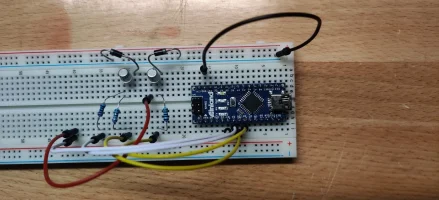
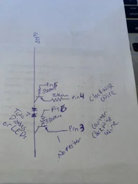
the basic circuit you want to set up is this:
IMG_4774.JPG

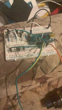
If successful your breadboard should look like a bowl of spaghetti (Note the stinger clockwise connection goes to pin 4 and counterclockwise to pin 3):
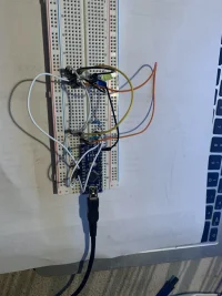
IMG_4773.JPG

Next you'll want to load up the code:
C++:
#include <EEPROM.h>

// comment this out when deployed:
#define DEBUG
// some arduinos have issues with pulling ground to some pins upon startup.
#define ERROR_OFFSET 1
#define INPUT_WAIT_TIME 500
#define STARTUP_WAIT_TIME 5000

#ifdef DEBUG
#define DEBUG_PRINT(x)  Serial.println (x)
#else
#define DEBUG_PRINT(x)
#endif

int memAddress = 0;
int memSetupAddr = 1;

const byte SMARTMODE = 0;
const byte ECOMODE = 1;
const byte COMFORTMODE = 2;
const byte SPORTMODE = 3;
const byte CUSTOMMODE = 4;

byte currentMode;
unsigned long t = 0; // current time
unsigned long p = 0; // previous time


void setup() {
  pinMode(3, INPUT_PULLUP); // clockwise input
  pinMode(4, INPUT_PULLUP); // counterclockwise input
  pinMode(5, OUTPUT);
  pinMode(6, OUTPUT);
  //If initial setup hasn't completed, set the default drive mode
  if (EEPROM.read(memSetupAddr) != 1) {
    // Write the default to permanent memory
    EEPROM.write(memAddress, COMFORTMODE);
    EEPROM.write(memSetupAddr, 1);
    currentMode = COMFORTMODE;
  } else {
    // Setup has completed read the current mode from permanent memory
    currentMode = EEPROM.read(memAddress);
  }
#ifdef DEBUG
  Serial.begin(9600);
#endif

  bool modechanged = true;
  delay(STARTUP_WAIT_TIME);
  switch(currentMode){
      case SPORTMODE:
        clockWise(1-ERROR_OFFSET);
        break;
      case CUSTOMMODE:
        clockWise(2-ERROR_OFFSET);
        break;
      case SMARTMODE:
        counterClockWise(2+ERROR_OFFSET);
        break;
      case COMFORTMODE:
        counterClockWise(ERROR_OFFSET);
        break;
      case ECOMODE:
        counterClockWise(ERROR_OFFSET);
        break;
      default:
        modechanged = false;
        break;
    }
    if (modechanged){
      DEBUG_PRINT("mode has changed.");
    }


  char s[50];
  sprintf(s, "setup mode: %s", modeText(currentMode));
  DEBUG_PRINT(s);
}

void loop() {
  char c[50];
  // constantly read the input pins increment/decrement
  // the drive mode and store it in permanent memory
  if (digitalRead(4) == LOW){
    t = millis(); // get current arduino uptime.
    if (t -  INPUT_WAIT_TIME > p){ // if 1 second has bassed since last reading
      if (currentMode >= CUSTOMMODE){
        currentMode = CUSTOMMODE;
      } else {
        currentMode++;
      }
      sprintf(c, "Clock Triggered, Current Mode: %s", modeText(currentMode));
      EEPROM.write(memAddress, currentMode);
      DEBUG_PRINT(c);
      p = t; // last reading is now, set p(revious) to current time
    }
  }
  if (digitalRead(3) == LOW){
    t = millis(); // get current arduino uptime.
    if (t - INPUT_WAIT_TIME > p){ // if 1 second has bassed since last reading
      if (currentMode <= SMARTMODE){
        currentMode = SMARTMODE;
      } else {
        currentMode--;
      }
      sprintf(c, "CClock Triggered, Current Mode: %s", modeText(currentMode));
      EEPROM.write(memAddress, currentMode);
      DEBUG_PRINT(c);
      p = t; // last reading is now, set p(revious) to current time
    }
  }

}

// simulate a clockwise turn of drive mode num times
void clockWise(int num){
  for(int i=0;i<num;i++){
    digitalWrite(5, HIGH);
    delay(250);
    digitalWrite(5, LOW);
    delay(250);
    DEBUG_PRINT("clockset");
  }
}

// simulate a counterclockwise turn of drive mode num times
void counterClockWise(int num){
  for(int i=0;i<num;i++){
    digitalWrite(6, HIGH);
    delay(250);
    digitalWrite(6, LOW);
    delay(250);
    DEBUG_PRINT("cclockset");
  }
}

char* modeText(byte s){
  char* r;
  switch(s) {
    case SMARTMODE:
      r = "Smart";
      break;
    case ECOMODE:
      r = "ECO";
      break;
    case COMFORTMODE:
      r = "Comfort";
      break;
    case SPORTMODE:
      r = "Sport";
      break;
    case CUSTOMMODE:
      r = "Custom";
      break;
     default:
      r = "";
  }
  return r;
}

Once programmed, make sure the car is NOT in ECO mode, and turn off the vehicle, plug the unit into a USB outlet on the car, and turn on the vehicle. If done correctly, you will see it go to sport mode, then back to comfort mode. it is now ready to record.


Troubleshooting:
  • If the drive mode doesn't match your input, using the stinger's drive mode selector, rotate it counter-clockwise 10 times with at least half a second between rotations, then reset the car then you can set your desired drive mode and it will remember properly
  • If you input drive modes faster than 500ms, adjust the #define INPUT_WAIT_TIME to a lower value, however too low may record multiple inputs if held down.
  • If nothing is happening, this is likely due to tapping the incorrect wires for the drive mode. there's a blue harness (M) that connects to a white harness (F) off the white harness there is a green wire with a blue stripe (counterclockwise), and a yellow with a green stripe (clockwise), these are your drive mode wires.
 
Last edited:
For the latest code, beta features, and bug fixes, I added this to my github
 
Don't have any positaps, and I'm not sure when I'll have time to break into my center console, but in the meantime does this breadboard look right?

Need to look up how to flash your code to the arduino, I've only ever done it once for my 3D printer and it's been a while.

also didn't have any 2K resistors, I'm guessing 2.2K will work.

IMG_20200824_194615.jpg
 
______________________________
Don't have any positaps, and I'm not sure when I'll have time to break into my center console, but in the meantime does this breadboard look right?

Need to look up how to flash your code to the arduino, I've only ever done it once for my 3D printer and it's been a while.

also didn't have any 2K resistors, I'm guessing 2.2K will work.

View attachment 49424
Looks great, to flash it just plug the USB into a computer and download the arduino software for your platform. Select the nano, and select the serial port it’s connected to, then upload the program. Let it run for a few seconds to ensure it does initial setup, then plug the USB into your car while it’s off, tap into the wires, and start her up. Let me know how it goes
 
Thanks a bunch for doing the design work on this, I'm excited to try making my own.

I spent a little time this morning re-writing the software to be able to use interrupts or polling, but I haven't tested it on my car yet, so typos are likely.

A nano only has 2 interrupt capable pins, so polling would be eventually required for ISG operation. Other chips like a teensy could use interrupts, but in a case like this, I think a tight polling loop is fine.

C:
#include <Arduino.h>
#include <EEPROM.h>
// how long we need to wait between changing modes automatically (in milliseconds)
#define OUTPUT_WAIT_TIME_MS 1000
// how long we need to hold the button down when changing modes automatically (in milliseconds)
#define OUTPUT_PULSE_TIME_MS 250
// how long it takes the car to start up (in milliseconds)
#define STARTUP_WAIT_TIME_MS 5000
// intput pins
#define CW_INPUT_PIN 2
#define CCW_INPUT_PIN 3
// output pins
#define CW_OUTPUT_PIN 5
#define CCW_OUTPUT_PIN 6
// enable debug messages
#define DEBUG
// debug print wrapper
#ifdef DEBUG
#define DEBUG_PRINT(x) Serial.println(x)
#else
#define DEBUG_PRINT(x)
#endif
#define INTERRUPTS
//#define POLLING
// memory address we store the mode in (not currently wear leveled, will handle ~100,000 mode changes)
int EEPROM_ADDRESS_MODE = 0;
// memory address we mark to signify first startup
int EEPROM_ADDRESS_INITIAL_SETUP = 1;
const byte MODE_FIRST = 0;
const byte MODE_SMART = 0;
const byte MODE_ECO = 1;
const byte MODE_COMFORT = 2;
const byte MODE_SPORT = 3;
const byte MODE_CUSTOM = 4;
const byte MODE_LAST = 4;
const byte MODE_IMPOSSIBLE = 255;
// global that stores current car mode
byte currentMode = MODE_IMPOSSIBLE;
// global that stores current target mode
byte targetMode = MODE_IMPOSSIBLE;
void update_eeprom(void)
{
  // only update eeprom if data is different (prevent eeprom wear)
  if (EEPROM.read(EEPROM_ADDRESS_MODE) != currentMode)
  {
    EEPROM.write(EEPROM_ADDRESS_MODE, currentMode);
    DEBUG_PRINT("EEPROM Update");
    DEBUG_PRINT(currentMode);
  }
}
// capture a cw physical knob turn
void knob_cw(void)
{
  currentMode -= 1;
  if (currentMode < MODE_FIRST)
    currentMode = MODE_FIRST;
}
// capture a ccw physical knob turn
void knob_ccw(void)
{
  currentMode += 1;
  if (currentMode > MODE_LAST)
    currentMode = MODE_LAST;
}
// simulate a clockwise turn of drive mode num times
void clockWise(int num)
{
  for (int i = 0; i < num; i++)
  {
    digitalWrite(CW_OUTPUT_PIN, HIGH);
    delay(OUTPUT_PULSE_TIME_MS);
    digitalWrite(CW_OUTPUT_PIN, LOW);
    delay(OUTPUT_PULSE_TIME_MS);
    DEBUG_PRINT("Automated CW");
  }
}
// simulate a counterclockwise turn of drive mode num times
void counterClockWise(int num)
{
  for (int i = 0; i < num; i++)
  {
    digitalWrite(CCW_OUTPUT_PIN, HIGH);
    delay(OUTPUT_PULSE_TIME_MS);
    digitalWrite(CCW_OUTPUT_PIN, LOW);
    delay(OUTPUT_PULSE_TIME_MS);
    DEBUG_PRINT("Automated CCW");
  }
}
void setup()
{
  // must use pins 2 and 3 for interrupts on an nano
  pinMode(CW_INPUT_PIN, INPUT_PULLUP); // clockwise input
  pinMode(CCW_INPUT_PIN, INPUT_PULLUP); // counterclockwise input
  pinMode(CW_OUTPUT_PIN, OUTPUT); // clockwise output
  pinMode(CCW_OUTPUT_PIN, OUTPUT); // counterclockwise output
  // if this is the first use set the default drive mode, car is expected to be in comfort mode
  if (EEPROM.read(EEPROM_ADDRESS_INITIAL_SETUP) != 1)
  {
    DEBUG_PRINT("First Boot");
    EEPROM.write(EEPROM_ADDRESS_MODE, MODE_COMFORT);
    EEPROM.write(EEPROM_ADDRESS_INITIAL_SETUP, 1); // mark initial setup as done
    targetMode = MODE_COMFORT;
  }
  else
  {
    DEBUG_PRINT("EEPROM Loaded");
    targetMode = EEPROM.read(EEPROM_ADDRESS_MODE);
    DEBUG_PRINT(targetMode);
    // car remembers eco and comfort settings
    if (targetMode == MODE_ECO || targetMode == MODE_COMFORT)
      currentMode = targetMode;
    else
      currentMode = MODE_COMFORT;
  }
#ifdef DEBUG
  Serial.begin(115200);
#endif
  // wait for car to start up
  delay(STARTUP_WAIT_TIME_MS);
  // change the car mode if needed
  if (targetMode < currentMode)
    counterClockWise(currentMode - targetMode);
  if (targetMode > currentMode)
    clockWise(targetMode - currentMode);
  currentMode = targetMode;
#ifdef INTERRUPTS
  // watch for the mode to change
  attachInterrupt(digitalPinToInterrupt(CW_INPUT_PIN), knob_cw, FALLING);
  attachInterrupt(digitalPinToInterrupt(CCW_INPUT_PIN), knob_ccw, FALLING);
#endif
}
void loop()
{
#ifdef POLLING
  // poll cw
  static bool previous_cw = true;
  bool cw = digitalRead(CW_INPUT_PIN);
  if (cw == false && cw != previous_cw)
    knob_cw();
  previous_cw = cw;
  // poll ccw
  static bool previous_ccw = true;
  bool ccw = digitalRead(CCW_INPUT_PIN);
  if (ccw == false && ccw != previous_ccw)
    knob_cw();
  previous_ccw = ccw;
#endif
  update_eeprom();
}
 
Last edited:
From interior to exterior to high performance - everything you need for your Stinger awaits you...
Forgive my ignorance, I'm just a big dumb mechanical engineer.

Why would I.S.G. disable require an interrupt pin?
I.S.G. resets every time you start the car, would it not be simle to just use another transistor to "push the I.S.G button" XXX miliseconds after start-up? After that it's off until you start the car back up, no need to watch it contunuously like the drive modes.
 
It's not the output that can benefit from an interrupt, but the input. You poll or use an interrupt to read the car button inputs so it can remember whatever it was set to the last time.

If you just want to blindly disable ISG every boot you will not have to do either.

In this case, polling inputs is likely going to be fine. The write to eeprom only takes a few milliseconds and human button input will be quite a bit longer than that, so you shouldn't risk missing user input and getting out of sync as long as you poll quickly.

In general structuring the code in a way that can be interrupt driven is easier to maintain, it separates reading the inputs from the action being performed.
 
Last edited:
Thanks a bunch for doing the design work on this, I'm excited to try making my own.

I spent a little time this morning re-writing the software to be able to use interrupts or polling, but I haven't tested it on my car yet, so typos are likely.

A nano only has 2 interrupt capable pins, so polling would be eventually required for ISG (Idle Stop and Go) operation. Other chips like a teensy could use interrupts, but in a case like this, I think a tight polling loop is fine.

C:
#include <Arduino.h>
#include <EEPROM.h>
// how long we need to wait between changing modes automatically (in milliseconds)
#define OUTPUT_WAIT_TIME_MS 1000
// how long we need to hold the button down when changing modes automatically (in milliseconds)
#define OUTPUT_PULSE_TIME_MS 250
// how long it takes the car to start up (in milliseconds)
#define STARTUP_WAIT_TIME_MS 5000
// intput pins
#define CW_INPUT_PIN 2
#define CCW_INPUT_PIN 3
// output pins
#define CW_OUTPUT_PIN 5
#define CCW_OUTPUT_PIN 6
// enable debug messages
#define DEBUG
// debug print wrapper
#ifdef DEBUG
#define DEBUG_PRINT(x) Serial.println(x)
#else
#define DEBUG_PRINT(x)
#endif
#define INTERRUPTS
//#define POLLING
// memory address we store the mode in (not currently wear leveled, will handle ~100,000 mode changes)
int EEPROM_ADDRESS_MODE = 0;
// memory address we mark to signify first startup
int EEPROM_ADDRESS_INITIAL_SETUP = 1;
const byte MODE_FIRST = 0;
const byte MODE_SMART = 0;
const byte MODE_ECO = 1;
const byte MODE_COMFORT = 2;
const byte MODE_SPORT = 3;
const byte MODE_CUSTOM = 4;
const byte MODE_LAST = 4;
const byte MODE_IMPOSSIBLE = 255;
// global that stores current car mode
byte currentMode = MODE_IMPOSSIBLE;
// global that stores current target mode
byte targetMode = MODE_IMPOSSIBLE;
void update_eeprom(void)
{
  // only update eeprom if data is different (prevent eeprom wear)
  if (EEPROM.read(EEPROM_ADDRESS_MODE) != currentMode)
  {
    EEPROM.write(EEPROM_ADDRESS_MODE, currentMode);
    DEBUG_PRINT("EEPROM Update");
    DEBUG_PRINT(currentMode);
  }
}
// capture a cw physical knob turn
void knob_cw(void)
{
  currentMode -= 1;
  if (currentMode < MODE_FIRST)
    currentMode = MODE_FIRST;
}
// capture a ccw physical knob turn
void knob_ccw(void)
{
  currentMode += 1;
  if (currentMode > MODE_LAST)
    currentMode = MODE_LAST;
}
// simulate a clockwise turn of drive mode num times
void clockWise(int num)
{
  for (int i = 0; i < num; i++)
  {
    digitalWrite(CW_OUTPUT_PIN, HIGH);
    delay(OUTPUT_PULSE_TIME_MS);
    digitalWrite(CW_OUTPUT_PIN, LOW);
    delay(OUTPUT_PULSE_TIME_MS);
    DEBUG_PRINT("Automated CW");
  }
}
// simulate a counterclockwise turn of drive mode num times
void counterClockWise(int num)
{
  for (int i = 0; i < num; i++)
  {
    digitalWrite(CCW_OUTPUT_PIN, HIGH);
    delay(OUTPUT_PULSE_TIME_MS);
    digitalWrite(CCW_OUTPUT_PIN, LOW);
    delay(OUTPUT_PULSE_TIME_MS);
    DEBUG_PRINT("Automated CCW");
  }
}
void setup()
{
  // must use pins 2 and 3 for interrupts on an nano
  pinMode(CW_INPUT_PIN, INPUT_PULLUP); // clockwise input
  pinMode(CCW_INPUT_PIN, INPUT_PULLUP); // counterclockwise input
  pinMode(CW_OUTPUT_PIN, OUTPUT); // clockwise output
  pinMode(CCW_OUTPUT_PIN, OUTPUT); // counterclockwise output
  // if this is the first use set the default drive mode, car is expected to be in comfort mode
  if (EEPROM.read(EEPROM_ADDRESS_INITIAL_SETUP) != 1)
  {
    DEBUG_PRINT("First Boot");
    EEPROM.write(EEPROM_ADDRESS_MODE, MODE_COMFORT);
    EEPROM.write(EEPROM_ADDRESS_INITIAL_SETUP, 1); // mark initial setup as done
    targetMode = MODE_COMFORT;
  }
  else
  {
    DEBUG_PRINT("EEPROM Loaded");
    targetMode = EEPROM.read(EEPROM_ADDRESS_MODE);
    DEBUG_PRINT(targetMode);
    // car remembers eco and comfort settings
    if (targetMode == MODE_ECO || targetMode == MODE_COMFORT)
      currentMode = targetMode;
    else
      currentMode = MODE_COMFORT;
  }
#ifdef DEBUG
  Serial.begin(115200);
#endif
  // wait for car to start up
  delay(STARTUP_WAIT_TIME_MS);
  // change the car mode if needed
  if (targetMode < currentMode)
    counterClockWise(currentMode - targetMode);
  if (targetMode > currentMode)
    clockWise(targetMode - currentMode);
  currentMode = targetMode;
#ifdef INTERRUPTS
  // watch for the mode to change
  attachInterrupt(digitalPinToInterrupt(CW_INPUT_PIN), knob_cw, FALLING);
  attachInterrupt(digitalPinToInterrupt(CCW_INPUT_PIN), knob_ccw, FALLING);
#endif
}
void loop()
{
#ifdef POLLING
  // poll cw
  static bool previous_cw = true;
  bool cw = digitalRead(CW_INPUT_PIN);
  if (cw == false && cw != previous_cw)
    knob_cw();
  previous_cw = cw;
  // poll ccw
  static bool previous_ccw = true;
  bool ccw = digitalRead(CCW_INPUT_PIN);
  if (ccw == false && ccw != previous_ccw)
    knob_cw();
  previous_ccw = ccw;
#endif
  update_eeprom();
}
Thanks so much for this rewrite, i do worry about your polling loop potentially detecting multiple inputs for a single turn, but once you deploy this on your own we'll find out! keep me in the loop() :D
 
So, I added the beta code for ISG memory support, and I added the circuit (needs a diode, a transistor, a 330ohm, and a few more wires, but just copy the pins 3 and 6 circuit on 7 and 8, and the ISG signal wire is on the white harness under the isg button and is a thin yellow wire near the driver side <not the thick yellow wire, thanks kia for color-codes> connect it to pin 7 with the rest of the circuit) I fully deployed this in the underside of my center console to do a week-long test to make sure everything works smoothly.

example image:
IMG_4823.JPG

If you're not following the github, here's the beta code. DO NOT COPY PASTE !!! THE VARIABLE FOR ISG IS JUST LOWER CASE I S G THE FORUM IS REPLACING THE TEXT I HOPE THE ADMINS FIX THIS BUG BECAUSE ITS WITHIN [ CODE ]
C++:
/**
* Kia Stinger Drive Mode Memory Module
*
* microcontroller programming in arduino (C++)
*
* by Joe Jackson 2020
* Version 0.9.1b
*/
#include <EEPROM.h>

// comment this out when deployed:
#define DEBUG

// beta stuff (uncomment to use beta features)
#define BETA


// some arduinos have issues with pulling ground to some pins upon startup.
#define ERROR_OFFSET 1

// Set time to wait between inputs in ms (recomended 500 or greater)
#define INPUT_WAIT_TIME 500
// Set time to wait before outputing memory to vehicle in ms (recommended 2000-5000)
#define STARTUP_WAIT_TIME 5000

#ifdef DEBUG
#define DEBUG_PRINT(x)  Serial.println (x)
#else
#define DEBUG_PRINT(x)
#endif

int memAddress = 0;
int memSetupAddr = 1;
int memFuture1Addr = 2;

const byte SMARTMODE = 0;
const byte ECOMODE = 1;
const byte COMFORTMODE = 2;
const byte SPORTMODE = 3;
const byte CUSTOMMODE = 4;

byte currentMode;
#ifdef BETA
bool isg = true;
#endif
unsigned long t = 0; // current time
unsigned long p = 0; // previous time


void setup() {
  pinMode(3, INPUT_PULLUP); // clockwise input
  pinMode(4, INPUT_PULLUP); // counterclockwise input
  pinMode(5, OUTPUT);
  pinMode(6, OUTPUT);
#ifdef BETA
  pinMode(7, INPUT_PULLUP); // ISG (Auto Start Stop) input
  pinMode(8, OUTPUT);
  if (!EEPROM.read(memFuture1Addr)) {
    isg = false; // disable ISG
  }
#endif
  //If initial setup hasn't completed, set the default drive mode
  if (EEPROM.read(memSetupAddr) != 1) {
    // Write the default to permanent memory
    EEPROM.write(memAddress, COMFORTMODE);
    EEPROM.write(memSetupAddr, 1);
    currentMode = COMFORTMODE;
  } else {
    // Setup has completed read the current mode from permanent memory
    currentMode = EEPROM.read(memAddress);
  }
#ifdef DEBUG
  Serial.begin(9600);
#endif

  bool modechanged = true;
  delay(STARTUP_WAIT_TIME);
  switch(currentMode){
      case SPORTMODE:
        clockWise(1-ERROR_OFFSET);
        break;
      case CUSTOMMODE:
        clockWise(2-ERROR_OFFSET);
        break;
      case SMARTMODE:
        counterClockWise(2+ERROR_OFFSET);
        break;
      case COMFORTMODE:
        counterClockWise(ERROR_OFFSET);
        break;
      case ECOMODE:
        counterClockWise(ERROR_OFFSET);
        break;
      default:
        modechanged = false;
        break;
  }
  if (modechanged){
    DEBUG_PRINT("mode has changed.");
  }
#ifdef BETA
  // if ISG is disabled in memory, send a signal. ISG is on by default.
  if (!isg){
    digitalWrite(8, HIGH);
    delay(250);
    digitalWrite(8, LOW);
    DEBUG_PRINT("ISG Disabled");
  }
#endif
  char s[50];
  sprintf(s, "setup mode: %s", modeText(currentMode));
  DEBUG_PRINT(s);
}

void loop() {
  char c[50];
  // constantly read the input pins increment/decrement
  // the drive mode and store it in permanent memory
  if (digitalRead(4) == LOW){
    t = millis(); // get current arduino uptime.
    if (t -  INPUT_WAIT_TIME > p){
      if (currentMode >= CUSTOMMODE){
        currentMode = CUSTOMMODE;
      } else {
        currentMode++;
      }
      sprintf(c, "Clock Triggered, Current Mode: %s", modeText(currentMode));
      EEPROM.write(memAddress, currentMode);
      DEBUG_PRINT(c);
      p = t; // last reading is now, set p(revious) to current time
    }
  }
  if (digitalRead(3) == LOW){
    t = millis(); // get current arduino uptime.
    if (t - INPUT_WAIT_TIME > p){
      if (currentMode <= SMARTMODE){
        currentMode = SMARTMODE;
      } else {
        currentMode--;
      }
      sprintf(c, "CClock Triggered, Current Mode: %s", modeText(currentMode));
      EEPROM.write(memAddress, currentMode);
      DEBUG_PRINT(c);
      p = t; // last reading is now, set p(revious) to current time
    }
  }
#ifdef BETA
  if (digitalRead(7) == LOW){
    t = millis(); // get current arduino uptime.
    if (t -  INPUT_WAIT_TIME > p){
      isg = !isg; // reverse the value from current.
      sprintf(c, "ISG Triggered, Current Mode: %s", isg ? "on" : "off");
      EEPROM.write(memFuture1Addr, isg);
      DEBUG_PRINT(c);
      p = t; // last reading is now, set p(revious) to current time
    }
  }
#endif
}

// simulate a clockwise turn of drive mode num times
void clockWise(int num){
  for(int i=0;i<num;i++){
    digitalWrite(5, HIGH);
    delay(250);
    digitalWrite(5, LOW);
    delay(250);
    DEBUG_PRINT("clockset");
  }
}

// simulate a counterclockwise turn of drive mode num times
void counterClockWise(int num){
  for(int i=0;i<num;i++){
    digitalWrite(6, HIGH);
    delay(250);
    digitalWrite(6, LOW);
    delay(250);
    DEBUG_PRINT("cclockset");
  }
}

char* modeText(byte s){
  char* r;
  switch(s) {
    case SMARTMODE:
      r = "Smart";
      break;
    case ECOMODE:
      r = "ECO";
      break;
    case COMFORTMODE:
      r = "Comfort";
      break;
    case SPORTMODE:
      r = "Sport";
      break;
    case CUSTOMMODE:
      r = "Custom";
      break;
     default:
      r = "";
  }
  return r;
}

 
Last edited:
frustratingly, despite being wrapped in the code brackets, the forum is replacing all the variables for the isg with the automatic text. please visit the github for the beta code.
 
______________________________
From interior to exterior to high performance - everything you need for your Stinger awaits you...
I really REALLY wish the forum would disable that stupid feature. Nobody wants it, and it screws up what people are saying all the time. (e.g. are you talking about Fiat Chrysler America in a thread about Dodge? Nope! Now you're talking about Forward Collision Assist!)

This is a super, super cool project and next time I run out to Micro Center I'll pick up a nano and give it a shot. I should have everything else I need around here already. I thought I had an arduino but I can't find it..
 
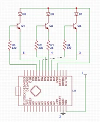
I know a ton of folks may have looked at my free-hand drawn diagram with confusion, so I actually sat down and made a real one for easier readability (dashed line is a connection). the pins are labeled:
  1. 12v power
  2. Ground
  3. Clockwise input (Yellow with green line)
  4. Counter Clockwise input (Blue with green line)
  5. ISG input (thin yellow)
Screen Shot 2020-08-26 at 5.46.37 PM.png
 
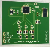
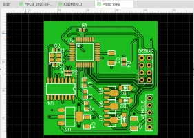
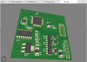
Little preview of a full pcb that does all of this.

IMG_4875.webp
 
Only thoughts that come to my mind would be potentially using the unused CPU pins for heated / cooled seats, steering wheel, and auto-hold memory (one module to do it all, instead of a pile from shark racing).

Maybe an undefined trigger input (actually two) would be useful for people who have a compustar with dual aux outputs (So a single button or remote input could automatically set everything to a defined state).

I assume U3 is a FTDI USB-Serial chip for field updates, with a USB Port on the backside? Otherwise, just a FTDI header would be handy.
 
From interior to exterior to high performance - everything you need for your Stinger awaits you...
Only thoughts that come to my mind would be potentially using the unused CPU pins for heated / cooled seats, steering wheel, and auto-hold memory.

Maybe an undefined trigger input (or two) would be useful for people who have a compustar with aux outputs.

I assume U3 is a FTDI USB-Serial chip for field updates, with a USB Port on the backside? Otherwise, just a FTDI header would be handy.

I had considered that. But probably going to wait for a future version.

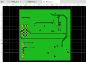
U3 is indeed a USB-Serial chip, which is only for the initial flash. Technically it could be used for field updates, but I’ve been refining the programming to have a final product, there is not a USB port, the D+ and D- pins will just have pins soldered in place for the initial flash, U10 is a very wide-range LDO so a spliced cable can connect to +12v, GND, D+ and D-

U1 is a ATMega328 which is the same microcontroller from the Arduino Nano
 
Last edited:
______________________________
Hello! Here’s the latest update still got a few things to check out but I’m almost ready to get this prototype sent out for manufacturing.
CEFC1103-A91C-4932-8E07-057DA1875CE6.webp17CD25B4-14F9-4C06-B50F-28A711879FBD.webpED9A6F56-DABD-46DD-9975-14E030C5415B.webp
 
Very nice! What software are you using for schematic capture and board layout?

George
 
From interior to exterior to high performance - everything you need for your Stinger awaits you...
Back
Top