Transfer case on AWD models: was it meant to be reliable ?

dgorbenko

Newish Member
Joined
May 5, 2022
Messages
18
Reaction score
18
Points
3
My transfer case failed and I disassembled it. Was very surprised to find out that there is no mechanism to disengage friction disks from steel, nor to engage them (squeeze them to create a lot of friction). The small electric motor attached to the case is an oil pump, also there is a sensor next to propeller shaft, which I suppose, counts rotations. There is no temperature sensor, and no way to reduce friction between disks. There is a wave disk spring which creates some tension between friction and steel disks.
Which means, afaik, there is no way to reduce heat generation if disks experience a lot of friction. Only oil pump (I hope it works all the times).

So, I wonder how the Kia detects any failures with transfer case ? In my case the wave disk spring had broken into 5 pieces, and the smallest piece was shredded into dust by gears. There was a nocking sound coming from the transfer case, and after I opened the case it smelled with burned oil. Btw, the plastic filter and plastic cap were also melted due to heat being generated by friction disks, and guess where these plastic details are located ? Right next to friction plates, there is 5-6mm distance between them. And of course, my Stinger didn’t show any light on a dash panel, all was fine expect this nocking sound. This failure happened after I pressed gas pedal to the floor. Kickdown.

Since friction disks are connected to propeller shaft, and steel disks to front shaft, and they are always under friction, at any moment the rear wheels spin faster/slower the than front ones there will be heat generation happen in the transfer case. This is why Kia dealers tend to blame tires in transfer case issues.

Now I’m looking for parts to fix my transfer case: friction disks, wave disk spring to press on friction package, plastic cap + filter.
If someone knows where to find them, please, let me know.
Thank you so much.
 
Last edited:
Btw, I was wrong, the sensor next to propeller shaft is a oil pressure sensor. This is how AWD ECU recognizes issues, I think.
 
What kind of expense is involved with a bunged up transfer case?
 
______________________________
What kind of expense is involved with a bunged up transfer case?
I don't know. It depends on the issue you may get. I'd say you need to order a new transfer case, which can be found for 2200$ or 1500$ + shipping from Korea. Or on eBay for the same price. There is no sense to buy used transfer case, because it may have burned friction disks (or something worse).

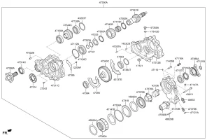
If you try to go with parts, try to googe: 47300-4J000 or 47300-4J010 (the old version, I guess).This is the transfer which Stinger has. You will easily find websites with diagram of transfer case. And as you will see many parts are discontinued, and currently I have a lot of problem ordering them. But it's still possible to find them around the world... In my case it may cost me 250$ + shipping.

But, as I said, no one sells them, even dealers. Which is such a shame - discontinued pars on relatively new vehicle ? And it's not only about Stinger, the Genesis G70/80/90 and many other cars suffer from this. Seems like they they don't want you to fix a transfer case, they want you to buy a new one.
 
Thanks. I know that I would just put a new one in. No gearhead here!
 
From interior to exterior to high performance - everything you need for your Stinger awaits you...
Eh? That's just a normal wet clutch. Your automatic transmission has five or six clutches that are exactly like that - always in motion and no "disengagement". They will last hundreds of thousands of miles as long as they stay lubricated and the apply is fast and solid.

The only downside to this design is that partial engagement (like trying to modulate front/rear power split) is really hard on that type of clutch. But I don't know if the stinger even attempts to do that - I think it's just fully on or fully off.

The wave steel is a cushion. Without that, the apply can be harsh, like a thunk. Some clutches will have a wave, some won't - just depends on the design and details. Broken wave plates are a thing that happens - generally a manufacturing fault. I don't think there's anything uniquely faulty or weak in the design. Sometimes shit breaks.

As for discontinued, when it comes to internals, manufacturers always hate providing internals and will discontinue as quickly as possible. I would expect assemblies to be available, but finding the right part number can be a chore. Often they'll deprecate a part number and it's hard to find the replacement.
If you're really serious about it, then go talk to your local transmission shops. They rebuild transfer cases also and have connections with the parts suppliers. Sooner or later the aftermarket will start making service parts for this transfer case.
 
Thank you for your comment ! It's very helpful especially regarding transmission shops.
I might be wrong regarding transmission clutches, but I assume they of course touch each other (like brake pads and rotor) but without pressure applied they don't transmit torque. The same I expected to see in the transfer case - some mechanism which creates pressure. But, if you say this is expected, then I need to google :)
 
Most motorcycles use a wet clutch pack. The bike on the left iirc used something like 10 friction plates and 9 steels plates sandwiched in an alternating configuration. The entire assembly bathed in motor oil (good old shell rotella 15w40). It works surprisingly well. Pull in the clutch just barely and it all disengages. With the clutch lever released, spring (5) loads up the assembly so all plates are locked.

youtube .com/watch?v=mxTSw3d5anE
 
I've only found one diagram of transfer case internals, and it's the normal terrible line drawing from OE parts catalogs. So it's hard to tell exactly what's going on, but I'm mostly confident it's this:
The input shaft runs straight through. There's a gear (47342b) on the input shaft (47341b) that runs on needle bearings (47115k) , so that gear can spin freely. The gear is meshed to the transfer gear (47343c) that goes to the output shaft (47386a via gear 47344c) . This gear also has a smaller toothed section that engages a basket (47380a). This basket will spin with the gear, which means it spins with the output shaft at all times.
The input shaft has a splined section that sits inside the basket. I can't tell which gets the steels and which gets the frictions, but it's almost always set up such that the steels engage the external teeth (basket, in this case) and the frictions engage the internal teeth (input shaft). There will be a piston in that basket (part 47318? maybe 47370B?). Actually, looking at the diagram, there's a chance they did it in a more complicated way and actuate the piston from the case. That would need some way to let the piston spin, but seems like maybe that's what's happening with 47376a and 43136? In either case, somewhere there's a piston that gets pushed by oil pressure from that little electric pump and squeezes all the plates together - same thing that the motorcycle clutch is doing with the springs.

So, apply the piston, and the gear is now locked to the input shaft. Release the piston, and the frictions/steels can spin, letting the gear spin at a different speed than the input shaft.

Post some pictures of the guts, especially the back portion that mounts the pump and the parts on the back half of the input shaft, and we'll know for sure how it works.
 
I am extremely curious....

How does the transfer case vary the torque distribution if it doesn't have the ability to adjust the force holding the clutches together?

Supposed to be near 80:20 rear bias in sport mode....

There must be something in the transfer case to make the clutch force variable to allow some slippage to the front wheels.
 
______________________________
From interior to exterior to high performance - everything you need for your Stinger awaits you...
I've only found one diagram of transfer case internals, and it's the normal terrible line drawing from OE parts catalogs. So it's hard to tell exactly what's going on, but I'm mostly confident it's this:
The input shaft runs straight through. There's a gear (47342b) on the input shaft (47341b) that runs on needle bearings (47115k) , so that gear can spin freely. The gear is meshed to the transfer gear (47343c) that goes to the output shaft (47386a via gear 47344c) . This gear also has a smaller toothed section that engages a basket (47380a). This basket will spin with the gear, which means it spins with the output shaft at all times.
The input shaft has a splined section that sits inside the basket. I can't tell which gets the steels and which gets the frictions, but it's almost always set up such that the steels engage the external teeth (basket, in this case) and the frictions engage the internal teeth (input shaft). There will be a piston in that basket (part 47318? maybe 47370B?). Actually, looking at the diagram, there's a chance they did it in a more complicated way and actuate the piston from the case. That would need some way to let the piston spin, but seems like maybe that's what's happening with 47376a and 43136? In either case, somewhere there's a piston that gets pushed by oil pressure from that little electric pump and squeezes all the plates together - same thing that the motorcycle clutch is doing with the springs.

So, apply the piston, and the gear is now locked to the input shaft. Release the piston, and the frictions/steels can spin, letting the gear spin at a different speed than the input shaft.

Post some pictures of the guts, especially the back portion that mounts the pump and the parts on the back half of the input shaft, and we'll know for sure how it works.
Can you post a link to the diagram you are referencing?
 
the TAC (Transfer Assembly Case) diagram is here:
www*DOT*hyundaipartsdeal*DOT*com/resources/encry/diagram/hpd/2020/large/09bdda5fb22802e34f4883c5a0bcb320/d20eabba2abd86c0efc45eaf5a515bc2.png
(replace *DOT* with ".", cause I can't post links)

>Post some pictures of the guts
Yes, going to to this today/tomorrow. Because I'm curious if I correctly understand how it works. Today I should have a wave disk spring delivery, and I'll have all parts to assemble TAC.
 
^^^ :rofl:
jeff bridges seabiscuit.webp
 
the TAC (Transfer Assembly Case) diagram is here:
www*DOT*hyundaipartsdeal*DOT*com/resources/encry/diagram/hpd/2020/large/09bdda5fb22802e34f4883c5a0bcb320/d20eabba2abd86c0efc45eaf5a515bc2.png
(replace *DOT* with ".", cause I can't post links)

>Post some pictures of the guts
Yes, going to to this today/tomorrow. Because I'm curious if I correctly understand how it works. Today I should have a wave disk spring delivery, and I'll have all parts to assemble TAC.
Thanks.

For easy viewing.

d20eabba2abd86c0efc45eaf5a515bc2.webp
 
I made a video where I tried to explain and show the internals of the transfer case.
I don't know why there so little videos on youtube on this transfer, so I decided to try upload one.

So, it seems like the wave spring pushes against friction disks and provides AWD feature all the time. Not sure how many % does it send to front wheels, but definitely not more than 50% :)
The only way how these disks may get overheated is through uneven amount of rotation on front and read wheels.
Also, if you got an AWD problem dashlight, it's either oil pressure sensor failure or oil pump failure. Both are easy to fix.

 
Last edited:
From interior to exterior to high performance - everything you need for your Stinger awaits you...
I made a video where I tried to explain and show the internals of the transfer case.
I don't know why there so little videos on youtube on this transfer, so I decided to try upload one.

So, it seems like the wave spring pushes against friction disks and provides AWD feature all the time. Not sure how many % does it send to front wheels, but definitely not more than 50% :)
The only way how these disks may get overheated is through uneven amount of rotation on front and read wheels.
Also, if you got an AWD problem dashlight, it's either oil pressure sensor failure or oil pump failure. Both are easy to fix.

Thanks for sharing the video.

I am at a total loss for how the torque split is supposed to be variable between sport mode and comfort mode...
 
______________________________
Thanks for sharing the video.

I am at a total loss for how the torque split is supposed to be variable between sport mode and comfort mode...
I wonder if the oil pump is the regulator here. Send more oil, create more lockup, more power is transferred to front wheels.
 
I think if you run the pump faster it would not help to send more torque to front wheels.

Look at this from another angle: if you split 50/50 torque between front and rear wheels then you need, well, equal or similar axles (the shaft which goes from differential to left or right wheel) on front and rear to hold the torque. But on AWD models the front axle is much more thinner than the rear one. I'd say front one is twice thinner, meaning it's designed to hold 3-4 times less torque (area = p * radius ^ 2).

There are just no signs to believe front wheels can get more torque at any moment.
 
From interior to exterior to high performance - everything you need for your Stinger awaits you...
Back
Top