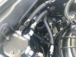
This is for if you’re looking to clean up your engine bay and get rid of the Posi-Taps. I have a tendency to over tighten Posi-Taps which weakens the plastic housing and always makes me second-guess whether the wires are making contact. Due to that issue, I felt it best to get ride of that weak link and create a true plug-n-play solution
This is only for the 3.3TT. I haven’t confirmed fitment for the 2.0.
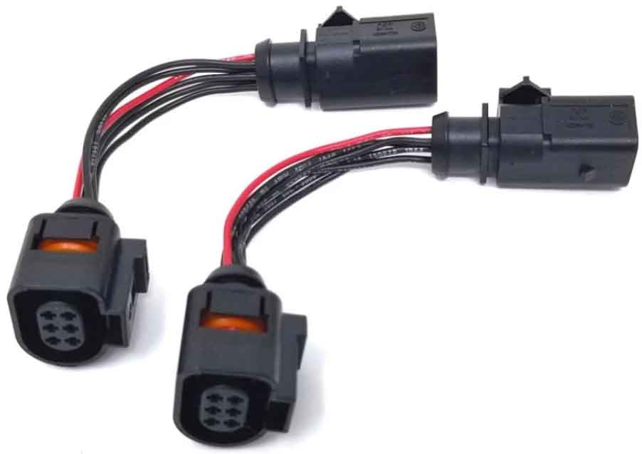
Pickup two LSU 4.9 extension harnesses, 6” or 12” are more than sufficient.
I ordered mine from here:
Home Bosch 6 way LSU 4.9 Extension Harness
You can also pick them up from here:
12 LSU 4.9 Bosch NTK Air Fuel O2 Sensor Extension Harness Cable LSU4.9 AEM AFR | eBay
Or if you want to go full DIY and create your own extension harness you can pickup the connectors here:
BOSH LSU 4.9 CONNECTOR + seals and terminals | eBay
From there you’ll want to splice and solder a wire lead to the harness or you can splice and solder the black fuel wires from the JB4 directly to the extension harness.
The red signal wire from the o2 sensors corresponds with this position from the plug. The red signal wire position is the same for both o2 sensors.

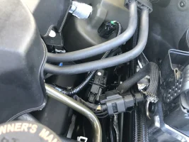
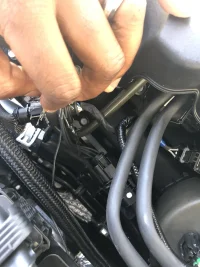
Simply pull back a bit of the wire sheath, tap that wire location, solder, tape, and heat shrink. Pull the sheath back over the wires to cover them. Plug the harness ends in, ensure they snap/click into place.
Do the same for the other side.
That’s it. You now have a fully plug and play JB4 and a system that’s fully removable with no traces of install.
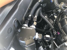
Next up may be a DIY on replacing the fittings, check valves, worm gear clamps, and vacuum lines the ADD W1 catch with -8AN and -6AN braided hoses, spring clamps, and AN hose finishers.
--EDIT--
I did a little research, I can basically make the harnesses for existing JB4 customers for the cost of the extension harnesses themselves + shipping.
What the end user will get is:
- x2 extension cables with PNP connectors
- x2 solder sleeve heat connectors
What the end user will need to do, aside from connecting the extension cables, is to take the single wire coming from each extension cable and the fuel wire from the JB4 and twist them together. Next, you'll take the supplied solder heat sleeve and slide it over the wires you just twisted together ensuring the solder joint is in the middle of the wire. Next, you'll take a lighter and heat the solder joint and the silicone ends to create a soldered joint and waterproof seal.
It will take you longer to read the paragraph above than to complete the steps.
I would go with solder sleeves because it's far more likely for an end user to have access to a lighter, or a gas stove, than a soldering iron. And given that I can strip back a part of the wire that needs to be exposed before shipping, the end user will not need a stripping tool.
If you fast forward this video to 2:47 -
- it is basically what I described above.
Just think of one wire as the JB4 fuel wire and the other being the attached wire coming from the o2 extension harness. Once the solder is melted, you have a complete PNP harness, no posi-taps needed.
This is only for the 3.3TT. I haven’t confirmed fitment for the 2.0.
Pickup two LSU 4.9 extension harnesses, 6” or 12” are more than sufficient.
I ordered mine from here:
Home Bosch 6 way LSU 4.9 Extension Harness
You can also pick them up from here:
12 LSU 4.9 Bosch NTK Air Fuel O2 Sensor Extension Harness Cable LSU4.9 AEM AFR | eBay
Or if you want to go full DIY and create your own extension harness you can pickup the connectors here:
BOSH LSU 4.9 CONNECTOR + seals and terminals | eBay
From there you’ll want to splice and solder a wire lead to the harness or you can splice and solder the black fuel wires from the JB4 directly to the extension harness.
The red signal wire from the o2 sensors corresponds with this position from the plug. The red signal wire position is the same for both o2 sensors.
Simply pull back a bit of the wire sheath, tap that wire location, solder, tape, and heat shrink. Pull the sheath back over the wires to cover them. Plug the harness ends in, ensure they snap/click into place.
Do the same for the other side.
That’s it. You now have a fully plug and play JB4 and a system that’s fully removable with no traces of install.
Next up may be a DIY on replacing the fittings, check valves, worm gear clamps, and vacuum lines the ADD W1 catch with -8AN and -6AN braided hoses, spring clamps, and AN hose finishers.
--EDIT--
I did a little research, I can basically make the harnesses for existing JB4 customers for the cost of the extension harnesses themselves + shipping.
What the end user will get is:
- x2 extension cables with PNP connectors
- x2 solder sleeve heat connectors
What the end user will need to do, aside from connecting the extension cables, is to take the single wire coming from each extension cable and the fuel wire from the JB4 and twist them together. Next, you'll take the supplied solder heat sleeve and slide it over the wires you just twisted together ensuring the solder joint is in the middle of the wire. Next, you'll take a lighter and heat the solder joint and the silicone ends to create a soldered joint and waterproof seal.
It will take you longer to read the paragraph above than to complete the steps.
I would go with solder sleeves because it's far more likely for an end user to have access to a lighter, or a gas stove, than a soldering iron. And given that I can strip back a part of the wire that needs to be exposed before shipping, the end user will not need a stripping tool.
If you fast forward this video to 2:47 -
Just think of one wire as the JB4 fuel wire and the other being the attached wire coming from the o2 extension harness. Once the solder is melted, you have a complete PNP harness, no posi-taps needed.
Attachments

Last edited:
")