[In Progress] Drive Mode Memory Module

budzique

Member
Joined
Jun 28, 2020
Messages
77
Reaction score
72
Points
18
Hi friends, so I'm currently working on a memory module for the drive mode selector. So far this will cost less than $50 with some assembly required.

DISCLAIMER: This is very technical and requires soldering and tapping into wires

So here we go. as far as parts required here's the list:
  • Arduino Nano [A000005]
  • 2x 5V diode [1N5339B]
  • 12V to 5V buck converter (I haven't decided on a part here yet)
  • 4x Positaps
  • A few lengths of wire. (prefer red, black, green and yellow for identification)
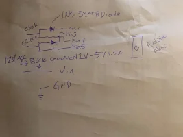
I've crudely drawn a circuit diagram for how you'll want to wire it. Keep in mind this is a work in progress I will have a final version that may not use any of this!


IMG_4567.webp

You'll want to code (see below) the arduino before wiring it into your car.

C++:
#include <EEPROM.h>

int memAddress = 0;
int memSetupAddr = 1;

const byte SMARTMODE = 0;
const byte ECOMODE = 1;
const byte COMFORTMODE = 2;
const byte SPORTMODE = 3;
const byte CUSTOMMODE = 4;

byte currentMode;
bool startup = true;

void setup() {
  pinMode(2, INPUT); // clockwise
  pinMode(3, INPUT); // counterclockwise
  pinMode(4, OUTPUT); // clockwise
  pinMode(5, OUTPUT); // counterclockwise
  if (EEPROM.read(memSetupAddr) != 1) {
    EEPROM.write(memAddress, COMFORTMODE);
    EEPROM.write(memSetupAddr, 1);
    currentMode = COMFORTMODE;
  } else {
    currentMode = EEPROM.read(memAddress);
  }
}

void loop() {
  if (startup){
    switch(currentMode){
      case SPORTMODE:
        clockWise(1);
        break;
      case CUSTOMMODE:
        clockWise(2);
        break;
      case SMARTMODE:
        counterClockWise(2);
        break;
      case COMFORTMODE:
      case ECOMODE:
      default:
        break;
    }
    startup = false;
  }
  if (digitalRead(2) == LOW){
    currentMode++;
    EEPROM.write(memAddress, currentMode);
  }
  if (digitalRead(3) == LOW){
    currentMode--;
    EEPROM.write(memAddress, currentMode);
  }
}

void clockWise(int num){
  for(int i=0;i<num;i++){
    digitalWrite(4, LOW);
  }
}

void counterClockWise(int num){
  for(int i=0;i<num;i++){
    digitalWrite(4, LOW);
  }
}
 
Hello, update time. A lot has changed with testing and I identified several flaws in my code and was able to simplify it a ton. So now, all you need is pins 2 and 3. and be sure to reference vehicle ground to GND if using USB to power it. There's still more to find out before a field test (No I have not yet plugged this into my own car) but I believe I am just one or two steps away.

Improvements:
  • Reduced used pins to 2 by using hybrid input/output
  • Prevent feedback loops without use of diodes
  • Prevent multiple readings per second of input by adding a 1 second timer between drive mode changes (this can be tuned later)
  • Improved reliability of drive modes by binding them to 5. (this prevents a bug where it stores the drive mode too high (eg 17: super ultra mega eco mode) thus losing ability to change to any mode except custom.
Code:
C++:
#include <EEPROM.h>

// comment this out when deployed:
#define DEBUG


#ifdef DEBUG
 #define DEBUG_PRINT(x)  Serial.println (x)
#else
 #define DEBUG_PRINT(x)
#endif

int memAddress = 0;
int memSetupAddr = 1;

const byte SMARTMODE = 0;
const byte ECOMODE = 1;
const byte COMFORTMODE = 2;
const byte SPORTMODE = 3;
const byte CUSTOMMODE = 4;

byte currentMode;
bool startup = true;
unsigned long t = 0; // current time
unsigned long p = 0; // previous time


void setup() {
  pinMode(2, INPUT_PULLUP); // clockwise input
  pinMode(3, INPUT_PULLUP); // counterclockwise input
  //If initial setup hasn't completed, set the default drive mode
  if (EEPROM.read(memSetupAddr) != 1) {
    // Write the default to permanent memory
    EEPROM.write(memAddress, COMFORTMODE);
    EEPROM.write(memSetupAddr, 1);
    currentMode = COMFORTMODE;
  } else {
    // Setup has completed read the current mode from permanent memory
    currentMode = EEPROM.read(memAddress);
  }
 
#ifdef DEBUG
  Serial.begin(9600);
#endif

  char s[50];
  sprintf(s, "setup mode: %x", currentMode);
  DEBUG_PRINT(s);
}

void loop() {
  if (startup){
    bool modechanged = true;
    switch(currentMode){
      case SPORTMODE:
        clockWise(1);
        break;
      case CUSTOMMODE:
        clockWise(2);
        break;
      case SMARTMODE:
        counterClockWise(2);
        break;
      case COMFORTMODE:
      case ECOMODE:
      default:
        modechanged = false;
        break;
    }
    startup = false;
    if (modechanged){
      DEBUG_PRINT("mode has changed.");
    }
  }
  // constantly read the input pins increment/decrement
  // the drive mode and store it in permanent memory
  if (digitalRead(2) == LOW){
    t = millis(); // get current arduino uptime.
    if (t -  1000 > p){ // if 1 second has bassed since last reading
      if (currentMode >= CUSTOMMODE){
        currentMode = CUSTOMMODE;
      } else {
        currentMode++;
      }
      EEPROM.write(memAddress, currentMode);
      DEBUG_PRINT("clock");
      p = t; // last reading is now, set p(revious) to current time
    }
  }
  if (digitalRead(3) == LOW){
    t = millis(); // get current arduino uptime.
    if (t - 1000 > p){ // if 1 second has bassed since last reading
      if (currentMode <= SMARTMODE){
        currentMode = SMARTMODE;
      } else {
        currentMode--;
      }
      EEPROM.write(memAddress, currentMode);
      DEBUG_PRINT("cclock");
      p = t; // last reading is now, set p(revious) to current time
    }
  }

}

// simulate a clockwise turn of drive mode num times
void clockWise(int num){
  for(int i=0;i<num;i++){
    digitalWrite(2, LOW);
    delay(100);
    digitalWrite(2, HIGH); // return to high after to prevent multiple outputs
  }
}

// simulate a counterclockwise turn of drive mode num times
void counterClockWise(int num){
  for(int i=0;i<num;i++){
    digitalWrite(3, LOW);
    delay(100);
    digitalWrite(3, HIGH); // return to high after to prevent multiple outputs
  }
}
 
It may be better to use interrupts to watch the pins and just sleep in the main loop. I can't remember how/if the arduino buffers digital input.
 
______________________________
It may be better to use interrupts to watch the pins and just sleep in the main loop. I can't remember how/if the arduino buffers digital input.
Arduino's void loop() runs well over 100hz, so I won't miss any inputs for sure, and while I could gain some efficiency in the programming it's self, the power draw is so negligible there's no real reason to. It's not a bad idea, but hardware interrupts is not something I've done with arduino so it would require research.
 
Update: through some field testing, I found memory storage of the current drive mode is working perfectly, as the drive mode changes the arduino stores it on it's eeprom, however, output is still not working, I'm going to source a pair of pulldown transistors and see if I can get the output. This may complicate the circuit I already spent time simplifying lol


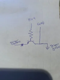
Example circuit for clockwise output. Will require pulldown transistor, 330kohm resistor, 5-16v diode as well as connections to both arduino and stinger ground:
IMG_4657.webp
 
From interior to exterior to high performance - everything you need for your Stinger awaits you...
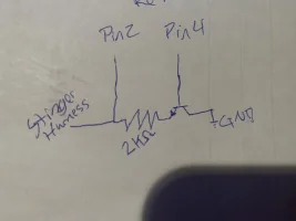
Hello friends, update time, the use of transistors has helped a ton, as well as a 2Kohm pull-down resistor, the current schematic and current code is below if you've been following along. The transistor is a basic N2222 transistor, and the resistor is 2Kohm, you'll need 2 of each. GND can be any ground. Currently when starting up there is an error I'm trying to debug that puts it into sport mode by it's self. I think we can work around this with some logic changes but I'm done for tonight. Below the schematic and code is a short 30 sec video showing what it currently can do. (It's processing at the time of posting so check back later if the video is unavailable)

IMG_4699.JPGCopy this circuit for pins 3 & 5
C++:
#include <EEPROM.h>

// comment this out when deployed:
#define DEBUG


#ifdef DEBUG
#define DEBUG_PRINT(x)  Serial.println (x)
#else
#define DEBUG_PRINT(x)
#endif

int memAddress = 0;
int memSetupAddr = 1;

const byte SMARTMODE = 0;
const byte ECOMODE = 1;
const byte COMFORTMODE = 2;
const byte SPORTMODE = 3;
const byte CUSTOMMODE = 4;

byte currentMode;
bool startup = true;
unsigned long t = 0; // current time
unsigned long p = 0; // previous time


void setup() {
  pinMode(2, INPUT); // clockwise input
  pinMode(3, INPUT); // counterclockwise input
  pinMode(4, OUTPUT);
  pinMode(5, OUTPUT);
  //If initial setup hasn't completed, set the default drive mode
  if (EEPROM.read(memSetupAddr) != 1) {
    // Write the default to permanent memory
    EEPROM.write(memAddress, COMFORTMODE);
    EEPROM.write(memSetupAddr, 1);
    currentMode = COMFORTMODE;
  } else {
    // Setup has completed read the current mode from permanent memory
    currentMode = EEPROM.read(memAddress);
  }

#ifdef DEBUG
  Serial.begin(9600);
#endif

  char s[50];
  sprintf(s, "setup mode: %x", currentMode);
  DEBUG_PRINT(s);
}

void loop() {
  if (startup){
    bool modechanged = true;
    switch(currentMode){
      case SPORTMODE:
        clockWise(1);
        break;
      case CUSTOMMODE:
        clockWise(2);
        break;
      case SMARTMODE:
        counterClockWise(2);
        break;
      case COMFORTMODE:
      case ECOMODE:
      default:
        modechanged = false;
        break;
    }
    startup = false;
    if (modechanged){
      DEBUG_PRINT("mode has changed.");
    }
  }
  // constantly read the input pins increment/decrement
  // the drive mode and store it in permanent memory
  if (digitalRead(2) == LOW){
    t = millis(); // get current arduino uptime.
    if (t -  1000 > p){ // if 1 second has bassed since last reading
      if (currentMode >= CUSTOMMODE){
        currentMode = CUSTOMMODE;
      } else {
        currentMode++;
      }
      EEPROM.write(memAddress, currentMode);
      DEBUG_PRINT("clock");
      p = t; // last reading is now, set p(revious) to current time
    }
  }
  if (digitalRead(3) == LOW){
    t = millis(); // get current arduino uptime.
    if (t - 1000 > p){ // if 1 second has bassed since last reading
      if (currentMode <= SMARTMODE){
        currentMode = SMARTMODE;
      } else {
        currentMode--;
      }
      EEPROM.write(memAddress, currentMode);
      DEBUG_PRINT("cclock");
      p = t; // last reading is now, set p(revious) to current time
    }
  }

}

// simulate a clockwise turn of drive mode num times
void clockWise(int num){
  for(int i=0;i<num;i++){
    digitalWrite(4, HIGH);
    delay(250);
    digitalWrite(4, LOW);
    delay(250);
    DEBUG_PRINT("clockset");
    //digitalWrite(2, HIGH); // return to high after to prevent multiple outputs
  }
}

// simulate a counterclockwise turn of drive mode num times
void counterClockWise(int num){
  for(int i=0;i<num;i++){
    digitalWrite(5, HIGH);
    delay(250);
    digitalWrite(5, LOW);
    delay(250);
    DEBUG_PRINT("cclockset");
    //digitalWrite(3, HIGH); // return to high after to prevent multiple outputs
  }
}
 
Last edited:
Nice work man, I'll be making one of these once it's finalized.

Out of curiosity, could the same Arduino also be used to disable auto start/stop?
 
Nice work man, I'll be making one of these once it's finalized.

Out of curiosity, could the same Arduino also be used to disable auto start/stop?
Yes, ISG works the same where the signal line is hot and pulled to GND when the button is pressed with the current layout it would be easy to just copy the circuit to pins 6 and 7 and a bit of extra code and it can remember your settings for ISG, you would then just tap into the ISG signal line.
 
Back
Top