Add W1 3.3v

Stormlasher

Active Member
Joined
Apr 19, 2018
Messages
144
Reaction score
35
Points
28
Location
Cape Cod
Can someone please explain this to me ..... i bought this can to eliminate the need to use 2 cans as it said. Well the installation instructions are here and to my dismay.......... call me stupid but this can dose no adherent help to stopping the need to using 2 catch cans. it just adds a secondary exhaust port for the pcv vaulve https://cdn.shopify.com/s/files/1/2611/6044/files/kia-stinger-3.3-w.pdf?138977371328060318 so tell me this adding the breather for the driver side, i understand not much oil comes from side but the answer is just stick a breather there? Looking to get some input on this to see if im missing something, . if not i am going to modify this can so its just a single and buy a secondary single. i mean really whats dose this do........ i just remove the hose from the air intake and feed it for a second vent for the pcv thats IT as far as i can see
 
@oddball posted this in another thread

The stock PCV has a check valve that, in my mind, is plenty good. I think an additional check valve is unnecessary unless you plan on going over 20psi boost. Adding one between the manifold and the can will keep pressure out of the can, but that's not necessary if the can is of at least decent quality and the hoses are clamped properly.

The VTA (vent to atmosphere - the filter on the fresh air tube) isn't emissions legal. Any state that does a visual inspection under the hood may notice that and fail you. The longer term problem is oil mist WILL occasionally come out of there. The classic car guys that do that on their breathers usually wrap a rag, sponge or similar around it to catch the oil before it makes a mess.

I'm not a fan of the single can. Doesn't make sense on how you can set it up properly. Those multi-connection cans are set up with a single "clean" air connection and two "dirty" air connections. When suction is applied to the clean air connection, dirty air is pulled in through the other two connections, goes through the element(s) and cleaner air goes out the clean connection.
A PCV system has two components - the PCV that provides crankcase vapor to the manifold, and fresh air intake (usually on the opposite side of the engine) so the air circulates through the crankcase.
The main catch can goes between the PCV and the manifold, with the manifold on the "clean" connection. Whenever there's manifold vacuum it'll pull crankcase vapors through the can and through the PCV valve, with the can catching the oil that will be suspended in there.
The secondary catch can goes between the fresh air tube and the intake tube with the intake tube on the "clean" connection. Whenever there is more crankcase vapor than the PCV can handle - which on a turbo car is just about every moment the car is under boost - crankcase vapor will be pushed out the fresh air pipe. It can't go in the manifold because that's pressurized. That crankcase vapor going out the fresh air pipe has oil in it, just like the other side. Previously that dumped straight into the intake track, so we're right back where we were before. Now you want that crankcase vapor to enter the "dirty" side of the can, then the clean side goes to the intake tube so the car just burns the leftover crankcase vapors (some oil will be left, plus some gas vapor, plus combustion byproducts). Putting a filter on the fresh air pipe will just cause oilly air to be sprayed all over the front of the engine every time the car is under boost.

Anyway, the whole point is air has to circulate *through* the crankcase. We figured this out in the early 60's. Every single OEM PCV system has had the same setup since then. With a single can you end up applying vacuum to both sides of the engine. Sure, you pull out the crankcase pressure and are emissions legal, but you don't circulate fresh air. This leads to the oil failing earlier than it should.

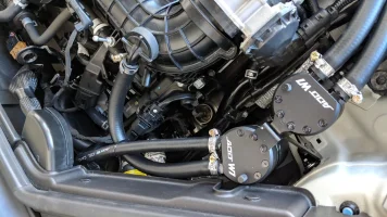
FWIW, the $30 Amazon cans are actually quite good. I added a wad of steel wool (and filter material to keep the steel wool out of the engine!) to help out the sintered bronze filter. The price of some of the cans out there really makes me wonder, especially with the limited info about the internals.
 
Here's how I understand it:

Stock:
PCV --> Intake manifold
Breather port --> Intake tract​

Dual can setup:
PCV --> (inlet) catch can 1 (outlet) --> intake manifold
Breather port --> (inlet) catch can 2 (outlet) --> intake tract

[Each blow-by source retains its own independent vacuum source]​

Dual inlet (single can) setup, such as yours:
PCV --> inlet port 1 on catch can
Breather port --> inlet port 2 on catch can
Catch can outlet --> intake tract
Plug --> intake manifold inlet

[Both blow-by sources share a single vacuum source (the intake tract)]
Oddball posted a very good read on this thread.
 
______________________________
LOL. We almost typed at same time. Your post summary is pretty helpful.
 
so long story short the diagram that was just released is not correct and its better to just go dual can?
 
From interior to exterior to high performance - everything you need for your Stinger awaits you...
How often should you empty out the can / whats the allowable oil capacity?
 
so long story short the diagram that was just released is not correct and its better to just go dual can?


I looked at it again and I don't think I understand it, so I'm removing my post which may be way off base. I'll let an expert chime in. Wish I could help more but I don't want to mislead you.
 
I may have misspoken. Is this can a dual inlet or dual outlet?
This is a dual inlet the one that I have and the directions I linked are the directions that they now supply for the can. I was told it’s to eliminate the need for 2 cans but the way I see it is I will still need 2 cans
 
______________________________
From interior to exterior to high performance - everything you need for your Stinger awaits you...
Okay, thought about it some more. This seems to be a dual-outlet setup and the plumbing seems to be this:

PCV --> inlet on catch can
outlet 1 --> check valve --> intake manifold
outlet 2 --> check valve --> intake tract

This would mean that the blow-by from the PCV will have two pathways to evacuate from the can when the PCV is open. I am having trouble figuring out why this is worthwhile. I suppose it may increase air flow through the crank case when the PCV is open, but if this increases the velocity of the air through the can, that may affect the can's ability to condense the contaminated air before it flows back out...into the intake manifold and intake tract, exactly where you wanted to clean the air before re-ingestion.

When the PCV is closed, the extra vacuum source will theoretically make no difference, as nothing should be flowing through the can. Thankfully they shouldn't pull from each other, assuming those check valves are there to prevent that.

I seem to remember seeing a dual-outlet setup with a t-junction, and it removed the PCV valve. I take it the instructions don't mention this?
 
This is a dual inlet the one that I have and the directions I linked are the directions that they now supply for the can. I was told it’s to eliminate the need for 2 cans but the way I see it is I will still need 2 cans

I only see one blow-by source going into the can in the instructions: the PCV. I also see two vacuum sources: intake manifold and intake tract. So unless I'm confused about inlet and outlet, that appears to be dual-outlet plumbing, even if it is designed to be a dual inlet can.

From what I can see, they seem to provide a vent-to-air (VTA) setup on the breather side, where you might have installed a second can. They used the factory vacuum source for the breather side as what appears to be the second vacuum source on the PCV side can.

Mind you, when I researched this I was focused on the 2.0T engine so I may be missing something on the 3.3T.

I am no expert on this, though I did lots of research before installing my setup. I saw a few different popular configurations, but nothing like the diagram you linked. I'm not following what they're trying to accomplish with this plumbing, though they should hopefully know a lot more than I do.
 
Check the can every tank of gas until you get a handle on the accumulation rate. I seem to be running about a teaspoon of oil per tank. The can doesn't have to be perfectly dry, so just empty it when it's convenient. Don't let it get more than 1/3 full though.

Note that these cans don't really have an "inlet" or "outlet" per se. They have some sort of obstruction that tries to knock the oil out of suspension *when* the air moves a certain direction. They're usually less effective going the other direction. What they call the "inlet" should have the dirty/oily air going in, and the "outlet" has cleaner air going out.

The problem is that in normal usage crankcase ventilation **goes both directions**. When the engine is under low stress the intake manifold is under vacuum and there's little blowby gasses. Air is circulated through the engine (in the driver valve cover, out the PCV) to keep the crankcase fresh. Under heavy loads there's more blowby - more than the PCV can handle even on a non-turbo, and a turbo pressurizes the manifold so nothing's going that direction - so the crankcase gasses have to come out the driver's valve cover.

The instructions that were linked will at least properly vent the crankcase under light loads. But under heavy load it'll spew oil over the front of the engine. Slowly, since these are new fancy engines, but it'll get dirty.

I haven't seen the inside of these cans, so this assumes that port on the side is the sole "dirty" port and the other two are "clean" ports. All of the cans that I've seen the internals on have two "dirty" ports and only one "clean" port.
 
...

The instructions that were linked will at least properly vent the crankcase under light loads. But under heavy load it'll spew oil over the front of the engine. Slowly, since these are new fancy engines, but it'll get dirty.

I haven't seen the inside of these cans, so this assumes that port on the side is the sole "dirty" port and the other two are "clean" ports. All of the cans that I've seen the internals on have two "dirty" ports and only one "clean" port.

Oddball, I'm on board with the plumbing in the instructions venting properly under light load, but do you see any benefit to connecting one of the presumed clean ports to the intake tract, or even having more than one vacuum source on a PCV side can? I can't see how it would help evacuate the blow by from the PCV--which already has vacuum from the IM--and it removes the vacuum source for the breather port.

On top of that, just sticking a filter on the breather side without a can without any baffling... I can see why you would expect oil spewing from there at some point. As a wild guess, maybe the intent was to provide an abundance of vacuum on the PCV side and ostensibly use the breather port just as an inlet to the crank case, but the fact that the PCV valve is still in place would seem to counteract that. To compound all of that, the crank case would be ingesting air filtered only by that little element instead of the factory intake.

I just can't make sense of the plumbing as shown in those instructions.
 
The Stinger cannot use a single can setup. You need a dual setup. Other wise you end up with a messy engine bay.
 
From interior to exterior to high performance - everything you need for your Stinger awaits you...
Putting a plain breather on one side and connecting the PCV to manifold vacuum is the good old hotrod method. That's how my '72 Cutlass is set up, but I've taken steps to manage oil migration (oil baffles in the valve cover, foam element in the breather, etc). And there's no turbo so the PCV is functional pretty much all the time expect WOT.
The intake track is a source of clean air and a place to dump pollutants to get burned by the engine. That's it. There is no appreciable vacuum or pressure in the intake tube between the filter and the turbo at any time. Running a line from the can to the intake track is useful for heavy load situations - that lets any vapor that comes out the passenger side of the engine get vented out to the intake. Only problem is you've got the same oily crankcase vapors coming out that little breather element at the same time. Since there's no vacuum applied to the PCV at this time there's no reason for the vapors to prefer going out the driver or passenger side. They'll go out whichever side is easier. And that plain breather is easier to push through than all the tubing and check valves.

Note that the PCV "valve" only has two purposes - it's a one-way check valve (don't want manifold air going into the crankcase! less bad with direct inject, but still) and regulates how much air is allowed to pass. When idling and the manifold is at high vacuum you don't want the engine running entirely on air from the crankcase. So the PCV specifically limits how much air it'll pass at different vacuum levels.
 
______________________________
I think I posted in another thread, but what you're looking at is why I went with the dual catch can setup. Oddball is explaining it ad nauseum, but the single can with dual inlets doesn't quite handle it "right", per se. You're venting one line to atmosphere, essentially, and sometimes that will include the very gunk you wanted to catch in the catch can.
 
Just installed the dual catch can setup. Very easy install. Maybe 45 minutes with pliers, a 10mm socket, a 7mm socket, a couple wire ties and some teflon tape. Mounting bracket, nuts, washers, proper length hoses and hose clamps all included. Thanks guys for a simple solution.
 

Attachments

  • 2018-10-30 14.06.43.webp
    2018-10-30 14.06.43.webp
    222 KB · Views: 65
how did you attach the bracket to the catch can with no screws??
 
Actually, the kit comes with a custom backet. You use the Allen head screws on the top of the cans to secure to the bracket.
 

Attachments

  • IMG_20181030_140654.webp
    IMG_20181030_140654.webp
    187.9 KB · Views: 31
From interior to exterior to high performance - everything you need for your Stinger awaits you...
Back
Top