
You are using an out of date browser. It may not display this or other websites correctly.
You should upgrade or use an alternative browser.
You should upgrade or use an alternative browser.
How to power front seat inside a house?
- Thread starter nVIceman
- Start date
I thought that is what was here. It's the only thing related to it I found.Do you have a wiring circuit diagram for the actual LCM? Similar to the schematic diagram for the IMS: http://www.kstinger.com/integrated_memory_seat_ims_unit-786.html
It is likely just a case of providing power and ground to the right pins for it as well.

boosted1g
Sustaining Member
Thats a diagram of the connectors but does not give me any of the circuit logic, on its own that diagram gives me the IN and OUT but nothing in the middle, in a nutshell it tells me switch-wire-pins -> mystery stuff??? -> motor-wire-pins.
I need a diagram like this one of the IMS, thats what let me see how the switches/relays are wired together:

Looking more at the S14 connector, it mentions ICU which is the Integrated Body Control Module (which is in the car).
If it needs data input (not just power/ground) from that then using the LCM directly is likely out of the question. However, it may be possible to bypass it.
I need a diagram like this one of the IMS, thats what let me see how the switches/relays are wired together:
Looking more at the S14 connector, it mentions ICU which is the Integrated Body Control Module (which is in the car).
If it needs data input (not just power/ground) from that then using the LCM directly is likely out of the question. However, it may be possible to bypass it.
______________________________
Okay. Well, I've looked over and over again many times going back a long ways. If that diagram is available that you're looking for, which I don't know why it wouldn't be, I haven't been able to find it. I'm not sure if someone that has one or if I need to get some kind of a wiring diagram information for the entire car and then just locate that particular section, but as of now I don't have any more info on that.Thats a diagram of the connectors but does not give me any of the circuit logic, on its own that diagram gives me the IN and OUT but nothing in the middle, in a nutshell it tells me switch-wire-pins -> mystery stuff??? -> motor-wire-pins.
I need a diagram like this one of the IMS, thats what let me see how the switches/relays are wired together:
View attachment 72368
Looking more at the S14 connector, it mentions ICU which is the Integrated Body Control Module (which is in the car).
If it needs data input (not just power/ground) from that then using the LCM directly is likely out of the question. However, it may be possible to bypass it.
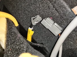
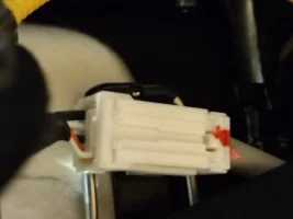
Couple of pictures here. The one with the white connector seems to have both a power and ground that comes from the main connector that I hadn't figured out what they were for. Same colors, but I'll need to verify those are those cables. Simply supplying power to them didn't make anything move. I undid a flap and was able to see these two gray connectors that plug together and the other picture that are just separated now. I was wondering as there seems to be a power and ground if the sleeve that goes the same direction as that white connector maybe leads to the lumbar control unit. If it does, maybe it's coming back down and going the way where the yellow sticker is and that leads to one of the motors. I may try supplying power there and see what happens.
Attachments
From interior to exterior to high performance - everything you need for your Stinger awaits you...
Here. The second picture has what is above everything in the other picture that you cannot see.Can you identify which connector # that is in the first picture you sent with the seat?
Attachments


RogueIV
Stinger Enthusiast
- Joined
- Jul 29, 2020
- Messages
- 865
- Reaction score
- 581
- Points
- 98
Again I'm going to warn you, DO NOT ATTEMPT TO DO ANYTHING WITHT HE WIRES WRAPPED IN YELLOW. Those are Airbags and they can and will pop if you put voltage on those wires.Couple of pictures here. The one with the white connector seems to have both a power and ground that comes from the main connector that I hadn't figured out what they were for. Same colors, but I'll need to verify those are those cables. Simply supplying power to them didn't make anything move. I undid a flap and was able to see these two gray connectors that plug together and the other picture that are just separated now. I was wondering as there seems to be a power and ground if the sleeve that goes the same direction as that white connector maybe leads to the lumbar control unit. If it does, maybe it's coming back down and going the way where the yellow sticker is and that leads to one of the motors. I may try supplying power there and see what happens.
RogueIV
Stinger Enthusiast
- Joined
- Jul 29, 2020
- Messages
- 865
- Reaction score
- 581
- Points
- 98
oops I see that it wasn't the one wrapped in yellow but just had a yellow label, still tred carfullyAgain I'm going to warn you, DO NOT ATTEMPT TO DO ANYTHING WITHT HE WIRES WRAPPED IN YELLOW. Those are Airbags and they can and will pop if you put voltage on those wires.
Thanks. Yeah, I was wondering the same thing with the sticker being yellow. They don't go through the yellow tubing though, so at the very least it's not consistent and is dangerous as a result.Again I'm going to warn you, DO NOT ATTEMPT TO DO ANYTHING WITHT HE WIRES WRAPPED IN YELLOW. Those are Airbags and they can and will pop if you put voltage on those wires.
The way the wires are routed though, really bizarre that would be airbag. Maybe I should take a picture to show you the way they route.
______________________________
From interior to exterior to high performance - everything you need for your Stinger awaits you...
Looking at the S14 lumbar control unit, I can see all of those color coded wires plugging into the connector that connects back to bottom. One is called Power Ground, others are the direction to move, so 6 in total across the 3 motors. Would connecting ground to Power Ground and then positive to the direction I want a motor to move work? The gaps are super tight just to try it out with. I may have to try a very limited number of copper strands stuck into the connector hole.
boosted1g
Sustaining Member
Without seeing a logical/circuit diagram of the LCM I really can not say what can and cannot be toggled through the LCM, I would just be "shooting blind"Looking at the S14 lumbar control unit, I can see all of those color coded wires plugging into the connector that connects back to bottom. One is called Power Ground, others are the direction to move, so 6 in total across the 3 motors. Would connecting ground to Power Ground and then positive to the direction I want a motor to move work? The gaps are super tight just to try it out with. I may have to try a very limited number of copper strands stuck into the connector hole.
Making a guess on the little bit of information I have, I suspect that the system uses reverse polarity. So on the UP/Down motor and the inflate/deflate, it uses +12v for one direction and the other direction uses -12V (hence the "power ground" wire because it could be used to ground the pos polarity, or supply `12V for the neg polarity)
Can you find the actual motor/inflators in the seat for lumbar (not just the wiring connectos)? Is there 2 or 3 wires going to them?
Have you tested putting power and ground to the pins in connecter C like I suggested? I am interested to know if that did get the IMS controlled motors working.
To clarify before i do it, I need power on c28 and c14, ground on c20, also power in ground in the b connector, but which ones? If it's the only two that I was able to trace back to the main connector and I just need one power and one ground to that, then I know what those are.
Forget clarifying. It worked! Once I made those five required connections instead of just the two I had been trying which I was able to access once I traced the wires all in the main connector, I was able to adjust five of the eight motors, just like I already had been able to do, but this time all at the same time using the buttons on the seat! Thanks for your assistance with that, that makes those adjustments much more helpful.
Now being that I figured out by now that the other adjustments weren't part of the memory unit, I'm not surprised to find out they still don't work. There must be some other connectors in the main connector that lead to that lumbar control unit, so just need to figure out what connections to make there and now I have hope that those can be made to work.
Also, when I first hooked up the power this way, the seat slid backwards quite a bit and then stopped. I've since removed power and put it back and it did not do it again, so I'm not sure if that was the memory of something it had, but as long as it doesn't do that every time I powered up, it would be a big deal. Although if it dispenses money every time it does that, I would be fine with it, because when I first powered it up a dime fell out.
Last edited:
boosted1g
Sustaining Member
GREATForget clarifying. It worked! Once I made those five required connections instead of just the two I had been trying which I was able to access once I traced the wires all in the main connector, I was able to adjust five of the eight motors, just like I already had been able to do, but this time all at the same time using the buttons on the seat! Thanks for your assistance with that, that makes those adjustments much more helpful.
Now being that I figured out by now that the other adjustments weren't part of the memory unit, I'm not surprised to find out they still don't work. There must be some other connectors in the main connector that lead to that lumbar control unit, so just need to figure out what connections to make there and now I have hope that those can be made to work.
Also, when I first hooked up the power this way, the seat slid backwards quite a bit and then stopped. I've since removed power and put it back and it did not do it again, so I'm not sure if that was the memory of something it had, but as long as it doesn't do that every time I powered up, it would be a big deal. Although if it dispenses money every time it does that, I would be fine with it, because when I first powered it up a dime fell out.
The seat moving back may have been the assisted exit feature (where the seat moves back when you turn off the car) still being stored in the memory module
______________________________
From interior to exterior to high performance - everything you need for your Stinger awaits you...
Learning from what you told me about what's to plug-in, I see the same body load and fuse pins for the lumbar control unit, as well as ground, so it would sound like if I put Power to both those pins and one to the ground, that the lumbar control unit would work.
boosted1g
Sustaining Member
Can you trace where the wiring goes from the lumbar and bolster switches on the seat. Does it go to another module, does it go straight to the motors or what?
I cant find any inflation control in the wiring diagrams or even parts lists.
The motors are reverse polarity, so to move it up you supply power to pin 4 and ground to pin 2, while to move it down you supply power to 2 and ground to 4.

If there is another control module then can hopefully figure it out.
Otherwise you can wire some relays between the switch wires and the motors and control it that way (basically building your own control module).
I cant find any inflation control in the wiring diagrams or even parts lists.
The motors are reverse polarity, so to move it up you supply power to pin 4 and ground to pin 2, while to move it down you supply power to 2 and ground to 4.
If there is another control module then can hopefully figure it out.
Otherwise you can wire some relays between the switch wires and the motors and control it that way (basically building your own control module).
The only logical place that the lumbar control unit cables are going (the 3 different adjustments both ways, so 6 total) would be to the seat switch button control panel S01-1. When I look at colors coming from lumbar control unit, they stay the same color once they connect into and out of the connector connecting back and bottom of seat. Then I look at those color coded cables and see what S01-1 has them as in the switch and every single one of them is the correct color for each adjustment, so that can't be a coincidence, so they must indeed go from S01-1 to the S14 lumbar control unit. The what seems like 3 power related cables go into the main connector as expected.
So far, I traced 2 of the 3. What looked like it had to be 3rd I couldn't find continuity from my multimeter, but it was hard enough to get it on the others with that connector and it facing the floor and near the floor, so it still may be right. I couldn't see it going elsewhere.
So far, I traced 2 of the 3. What looked like it had to be 3rd I couldn't find continuity from my multimeter, but it was hard enough to get it on the others with that connector and it facing the floor and near the floor, so it still may be right. I couldn't see it going elsewhere.
boosted1g
Sustaining Member
Ok looking at the connector diagrams of S14, pin 12 is a fused input, but pin 11 comes from power switch relays built into the ICU (the "fuse box" in drivers kick panel). These switches are something that the car uses instead of relays
Thus without the ICU, it looks like you wont be able to use the Lumbar Motor to control it.
You can however build your own controller using a 4 channel 12v relay board.
I made a diagram if you wanted to go this route:
View attachment 72411
Thus without the ICU, it looks like you wont be able to use the Lumbar Motor to control it.
You can however build your own controller using a 4 channel 12v relay board.
I made a diagram if you wanted to go this route:
View attachment 72411
Thanks. Do you think it's worth it and safe trying to hook it up the way I describe to see if it would work?Ok looking at the connector diagrams of S14, pin 12 is a fused input, but pin 11 comes from power switch relays built into the ICU (the "fuse box" in drivers kick panel). These switches are something that the car uses instead of relays
Thus without the ICU, it looks like you wont be able to use the Lumbar Motor to control it.
You can however build your own controller using a 4 channel 12v relay board.
I made a diagram if you wanted to go this route:
View attachment 72411
Does this relay board have a way to still use the buttons on the seat? I don't know how to read that diagram for how to make that work. Is it simple?
From interior to exterior to high performance - everything you need for your Stinger awaits you...